Editing Sketch |
  
|
Editing Sketch |
|
Sketch editing is done by the command "ESK: Edit Sketch". The command is called by one of the following ways:
Keyboard |
Textual Menu |
Icon |
<ESK> |
"Edit|Draw|Sketch" |
|
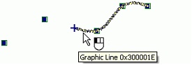
The command can also be called by pointing at a sketch entity in the command waiting mode and clicking ![]() , or right clicking
, or right clicking ![]() and selecting the item "Edit" in the context menu. Alternatively, the editing command can be accessed directly from the sketch creation command by selecting the option
and selecting the item "Edit" in the context menu. Alternatively, the editing command can be accessed directly from the sketch creation command by selecting the option ![]() .
.
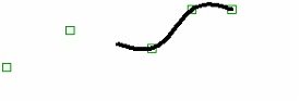
Sketch lines are treated as regular graphic lines. Thus, for their editing it is also possible to use the command “EG: Edit Graphic Line”.
After invoking this command, the following choices become available:
|
<*> |
Select All Elements |
|
<R> |
Select element from list |
|
<Esc> |
Exit command |
After invoking this command, a user can select the sketch line by pointing at it with the cursor and pressing ![]() . Selected element will be highlighted. Several elements can be chosen either by using selection with a window or by selecting successively several elements with the help of <Shift>+
. Selected element will be highlighted. Several elements can be chosen either by using selection with a window or by selecting successively several elements with the help of <Shift>+![]() . To undo selection of the element, the mouse
. To undo selection of the element, the mouse ![]() together with the pressed left key <Ctrl> can be used.
together with the pressed left key <Ctrl> can be used.
After choosing one or several sketch lines the following options will be available in the auto-menu:
|
<P> |
Set selected Element(s) Parameters |
|
<Alt+P> |
Copy Properties from Existing Element |
|
<I> |
Select Other Element |
|
<Del> |
Delete selecting Elemet(s) |
|
<Esc> |
Cancel selection |
If only one line is selected, the following option also appears in the automenu:
|
<O> |
Create Name for selected Element |
When editing sketch lines, please pay attention to the status of the ![]() icon in the system panel. If it is disabled, then editing will be done in the sketching mode. When the option is enabled, editing will be done in the automatic parameterization mode. In this mode, just like when creating a sketch, the system will be slipping construction elements tied by parametric relations beneath the edited lines. In addition, the system will attempt to parameterize not only the edited elements themselves, but also the lines that will be employed for the editing. For example, if the position of one of a sketched line segment nodes is changed in the automatic parameterization mode by defining its new position with an object snap to another sketched line, then construction lines will be slipped beneath both segments.
icon in the system panel. If it is disabled, then editing will be done in the sketching mode. When the option is enabled, editing will be done in the automatic parameterization mode. In this mode, just like when creating a sketch, the system will be slipping construction elements tied by parametric relations beneath the edited lines. In addition, the system will attempt to parameterize not only the edited elements themselves, but also the lines that will be employed for the editing. For example, if the position of one of a sketched line segment nodes is changed in the automatic parameterization mode by defining its new position with an object snap to another sketched line, then construction lines will be slipped beneath both segments.
Editing a Line Segment
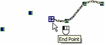
After selecting a line segment, select one of the segment nodes, the one to move. At this moment, new coordinates can be defined for the selected node in the property window. Besides, after selecting the node, the segment starts rubberbanding. The rubberbanding image defines the new position of the segment being edited. Rubberband the segment by the mouse to the desired position and click ![]() . This fixes the segment in the new position.
. This fixes the segment in the new position.
Editing a Circle, Ellipse, Arc and Elliptical Arc
If the selected element is a circle, ellipse or an arc (except an arc through three points), the second click ![]() on the selected entity launches the mode of editing the radius of the circle, ellipse or arc. A new value of the radius (diameter) can also be assigned via the property window or by rubberbanding the entity image to the desired position and clicking
on the selected entity launches the mode of editing the radius of the circle, ellipse or arc. A new value of the radius (diameter) can also be assigned via the property window or by rubberbanding the entity image to the desired position and clicking ![]() .
.
This way of editing is not suitable for an arc constructed through three points, and an elliptic arc. In this case, after selecting the arc, you need to select a node the arc is passing through, and move it to the desired position or enter the new placement coordinates of the node in the property window.
There is yet another way to modify any type of an arc or fillet. Select one of the end nodes of the selected arc, and then move the rubberbanding image of the arc into the desired position.
After selecting the arc of a circle an additional option becomes available in the automenu:
|
<Tab> |
Change Arc Direction |
This option replaces the selected arc with another arc of the same circle. When applying this option to the arc constructed by 3 points, the middle (second) node of the initial arc is automatically removed.
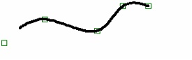
Editing Spline
After selecting a spline, the automenu gets an additional option:
![]() <Ctrl+X> Switch to "Insert Point" mode
<Ctrl+X> Switch to "Insert Point" mode
This option allows adding an additional point to a spline. After calling the option, select a spline node nearest to the additional node location. Then pick the side where the new node should be created with respect to the selected node, and then define its position.
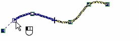
To edit an existing node, select it after selecting the spline. The node and the whole spline will start rubberbanding following the pointer. The new position of the node can be specified by simply moving the pointer to any location and clicking ![]() , or by specifying new coordinates of the node in the property window. The same window provides for entering the new weight value of the node (for splines by control polygon), as well as the number of spline segments.
, or by specifying new coordinates of the node in the property window. The same window provides for entering the new weight value of the node (for splines by control polygon), as well as the number of spline segments.
To delete an existing spline node, select the node and then use the option ![]() .
.
When editing a spline that was divided or trimmed, one can also change the position of the trimming points (the intersection points) of the spline image. These points are highlighted when the spline is selected, and become available for selection. The selected point can be moved along the spline and fixed at a new position by clicking ![]() .
.
When selecting the open spline for editing by nodes, the options for specifying directions of the tangent vectors for the spline end points will be also available in the automenu:
|
<F> |
Set direction at Spline start |
|
<E> |
Set direction at Spline end |