Bend


Bend |
|
To create bending at sheet bodies SMB: Bend operation is used:
Icon |
Ribbon |
|---|---|
|
Sheet Metal → Bend |
Keyboard |
Textual Menu |
<SMB> |
Operation > Sheet Metal > Bend |
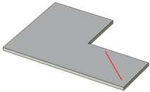
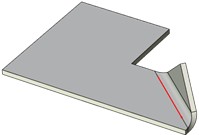
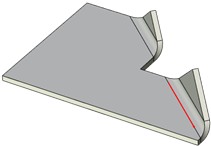
When bending the initial workpiece is bent along the base line only, without cutting or removing any of its parts. In this type of folding the bending line is formed by extending the base line set as a segment sideways to crossing the base face side edges. There are two variants possible to extend the base line.
|
|
|
Workpiece |
Not to fold all the face |
To fold all the face |
When creating a bending it is impossible to set indents from the base line ends.
Command parameters
Command parameters are general for sheet metal commands and are described in the corresponding subsection above.
The command automenu options are:
|
<Ctrl+Enter> |
Finish input |
|
<P> |
Set entity Parameters |
|
<X> |
Exit command |
|
<F5> |
Preview Operation Result |
|
<L> |
Select Line |
|
<W> |
Draw Profile |
|
<E> |
Select first Vertex or 3D Node |
|
<S> |
Select second Vertex or 3D Node |
|
<A> |
Cancel Selection |
|
<D> |
Change the part to be bend |
Finish input. Builds a geometry according to the given parameters. In case there are not enough parameters set, the option is not available.
Set entity Parameters. Calls a standard dialog of 3D modeling command parameters.
Exit command. Shuts down the command with cancelling all the set parameters.
Preview Operation Result. Enables/disables the standard option of 3D modeling commands review.
Select Line. Selects a line determining the base bending line. The line can be set basing on the path, profile or the trace.
Draw Profile. Sets the base bending line in transparent mode. When choosing the option you should set the workpiece face (the system automatically switches to drawing at the selected work plane mode), after which you should create the profile outline at the selected face. The outline should be a segment. When exiting the drawing at the selected work plane mode the profile created will be selected automatically.
Select first Vertex or 3D Node. Chooses the first point determining the base bending line.
Select second Vertex or 3D Node. Chooses the second point determining the base bending line.
Cancel Selection. Cancels all the elements selected and clears the operand window.
Change the part to be bend. When folding one part of the workpiece remains stationary and the second one moves in space according to the set folding parameters. This option enables users to swap the moving and the stationary parts of the workpiece.
Creating the bend
A typical procedure when creating a bend is:
●To create the base line
●To select whether to bend all the face or at the extension to the nearest edges
●To change the bent part if necessary
●To set the available standard bending operations parameters
●Finish entering.