Bridge Bend


Bridge Bend |
|
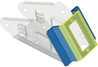
To build a bridge between two sheet parts SM2: Bridge Bend operation is used:
Icon |
Ribbon |
|---|---|
|
Sheet Metal → Bridge Bend |
Keyboard |
Textual Menu |
<SM2> |
Operation > Sheet Metal > Bridge Bend |
The operation enables users to create transition geometry with the given folding radius between the edges of the two sheet bodies of equal thickness, combining these bodies into one.
There are two variants of a bridge realized.
|
Z/U From |
|
Folded |
There are three ways to build a bridge.
|
By both edges |
|
By start edges |
|
By end edges |
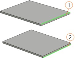
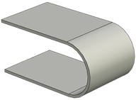
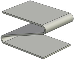
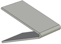
Transition variants of U-shape.
|
|
|
1 – initial edge, 2 – final edge |
U-shape, 2 folds |
U-shape, 1 fold |
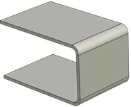
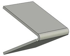
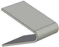
Creating a transition of Z-shape.
|
|
1 – initial edge, 2 – final edge |
Z-shape |
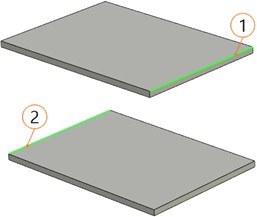
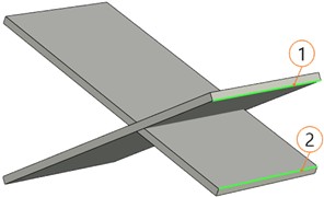
In case of two sheet bodies intersecting it is possible to build a U-shape transition with one fold between them.
|
|
1 – initial edge, 2 – final edge |
U-shape, 1 fold |
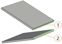
If two sheet bodies are inclined towards each other (the edges for building the bridge are still parallel), there are two types of a U-shape transition with one fold possible.
|
|
|
1 – initial edge, 2 – final edge |
By displacement |
By radius |
Conditions of building a bridge
Several conditions are to be followed when building a bridge between two sheet bodies.
●Sheet bodies must be of equal thickness.
●Only straight edges can be used for building the bridge.
●The initial and the final edges must belong to different sheet bodies.
●The initial and the final edges must be parallel.
Command parameters
Z/U From. The bridge will have two bending radii at each of the selected edges.
Folded. The bridge will have one bending radius which is equal to half the distance between inner edges of the parts being connected.
By both edges. The bridge shape will depend on both edges. The bridge symmetry axis will be determined by central points of the selected edges.
By start edges. The bridge shape will be determined by the first of the selected edges. The bridge symmetry axis will run through the centre of the first edge and will be perpendicular to the first edge.
By end edges. The bridge shape will be determined by the second of the selected edges. The bridge symmetry axis will run through the centre of the second edge and will be perpendicular to the second edge.
Other command parameters are general for sheet metal commands and are described in the corresponding subsection above.
The command automenu options are:
|
<Ctrl+Enter> |
Finish input |
|
<P> |
Set entity Parameters |
|
<X> |
Exit command |
|
<F5> |
Preview Operation Result |
|
<F> |
Select start edge |
|
<S> |
Select end edge |
Finish input. Builds a geometry according to the given parameters. In case there are not enough parameters set, the option is not available.
Set entity Parameters. Calls a standard dialog of 3D modeling command parameters.
Exit command. Shuts down the command with cancelling all the set parameters.
Preview Operation Result. Enables/disables the standard option of 3D modeling commands review.
Select start edge. Selects the edge at the first body.
Select end edge. Selects the edge at the second body.
Bridge building
A typical procedure when building the bridge is:
●Choose the bridge variant: Z/U From, Folded.
●Select the edge at the first body.
●Select the edge at the second body.
●Choose the building variant: By both edges, By start edges, By end edges.
●Set general sheet material parameters.
●Finish entering.