Deformation by Surface


Deformation by Surface |
|
General Information
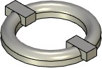
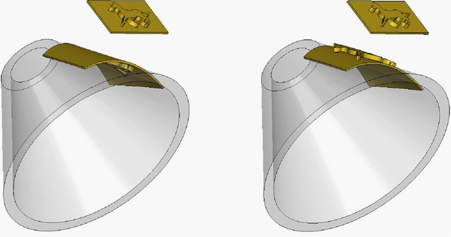
In the deformation by surface the deformation law is defined by two surfaces: the source and the target one. The deformation function is constructed in such a way that the source surface is reflected onto the target one.
In general case, the source and the target surfaces may not belong to the deformed body. In practice, however, it is often convenient to choose one of the faces of the deformed body to be the source surface. In this case, the deformation function is constructed in such a way as to provide the «bend» of the deformed body onto the target surface.
A solid or a sheet body can be selected as the deformed body.
The source and the target surfaces can be specified by face, 3D profile or a sheet body. The sheet body, specified as the source body, must consists of one face. For defining the target surface, the polyhedral sheet body can be used, however, its faces must have a continuous joint on the tangent plane.
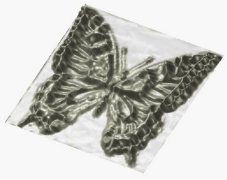
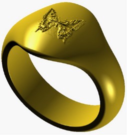
For a source surface, it is not recommended to select surfaces with a complicated geometry, for example, faces with a picture “pressed out” on them. When transforming such face to the target one, the loss of the face geometry may occur. In such cases, as a source surface, it is better to define, for example, the 3D profile drawn in the plane containing the boundaries of the complicated face.
For defining the deformation function more precisely, base points are specified on the source and the target surfaces. For each surface, three points lying on the surface are specified. The points can be specified with the help of 3D nodes, vertices or other 3D objects capable of defining a 3D point. The specified points are not supposed to lie on the same line. The order in which the points on the source and the target surfaces are specified has to coincide.
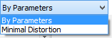
Two transformation methods are used when performing the deformation by surface:
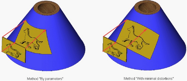
-By parameters – transformation with superposition of the base points of the surfaces. With that deformation method, the points on the source surface exactly go into the points on the target surface. When using this method, the target surface cannot have more than one face;
-With minimal distortions – transformation with preserved geometric distances between points of the source surface. This method gives minimal distortions, if the distances between the first two points on the source and the resulting surfaces coincide. If the distances do not coincide, the distances are recalculated with the corresponding similarity factor. The distances are measured as the lengths of the normal sections.
The method “with minimal distortions” can be applied in cases when the target surface consists of a collection of faces (sheet body). It provides the superposition without irregularities which are common for the interior surface parametrization.
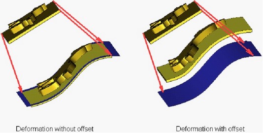
When creating the deformation by surface, the offset from the target surface can be specified. In this case, upon forming the deformation function, the source surface will be transformed not to the target surface, but to the equidistant to it surface with the specified offset.
As a result of the deformation, the resulting body may turn out to lie on either side of the target (or equidistant to it) surface. The placement of the body can be quickly changed with the help of the button in the dialog of the command's properties.
Creating Deformation by Surface
For creating deformation by surface, the command “3DRF: Deformation by Surface” is used:
Icon |
Ribbon |
|---|---|
|
3D Model → Special → Deformation → Deformation by Surface |
Keyboard |
Textual Menu |
<3DRF> |
Operation > Deformation > Deformation by Surface |
To create deformation by surface, it is necessary:
1.Select deformed body;
2.Select the source surface of deformation;
3.Define the base points on the source surface;
4.Select the target surface of deformation;
5.Define the base points on the target surface;
6.Specify deformation method (“By parameters” or “With minimal distortions”);
7.Specify offset (if necessary);
8.Complete operation creation by pressing ![]() .
.
Selection of Deformed Body and Source Surface
After invoking the command, in the automenu the options for specifying necessary initial data will appear. For selection of the deformed body, the following option is used:
|
<O> |
Select Body to Deform |
This option is turned on by default upon the entry into the command. The deformed body is selected with the help of ![]() in the 3D window or in the tree of the 3D model. The selected body is highlighted.
in the 3D window or in the tree of the 3D model. The selected body is highlighted.
After that, the system will prompt the user to select the source surface of deformation:
|
<T> |
Select Source Surface |
The drop down list of this option contains the list of 3D elements capable of defining the source surface of deformation: face, sheet body, 3D profile. The selected surface will be marked in the 3D scene.
Selection of Correspondence Points on Deformed Body and Source Surface
After selection of the source surface, the options for selecting three base points of the source surface will be successively activated in the automenu:
|
<L> |
Select First Point on Source Surface |
|
<K> |
Select Second Point on Source Surface |
|
<G> |
Select Third Point on Source Surface |
The drop down lists of these options contain filters for selection of the 3D elements capable of defining a 3D point.
For specifying the target surface, the following option of the automenu is used (it becomes active automatically after specifying the base points of the source surface):
|
<M> |
Select Target Surface |
This option also has a drop down list with the filters for selection of the different types of the 3D elements capable of defining a surface.
After selection of the target surface, its base points need to be specified successively:
|
<R> |
Select First Point on Target Surface |
|
<F> |
Select Second Point on Target Surface |
|
<B> |
Select Third Point on Target Surface |
Specifying Deformation Parameters
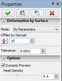
The deformation mode is selected with the help of the parameter “Mode” in the dialog of the command's properties. The offset of the source surface with respect to the target one is specified with the help of the parameter “Offset”. The placement of the deformed body with respect to the target surface can be changed with the help of the button |
|
Options in Deformation Operations
In the process of specifying/editing parameters of deformation, the future result of the current operation is dynamically shown in the 3D window. For speeding up the work, the dynamic preview can be turned off by taking off the flag “Dynamic Preview” in the command's properties window.
An additional parameter “Mesh Density” controls accuracy of the mesh used for visualization of the result of the deformation. The increase in the mesh density leads to slower regeneration of the bodies in the scene but increases accuracy of the drawing. |
|
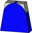
If you disable option Mark body, the body is no longer highlighted in the scene, which simplifies visual perception of the deformed object.
On |
Off |
The Live update option allows to watch deformations of the body in real time. Deactivating the option accelerates recalculation because solid body updating is not required.