Normal Cutout


Normal Cutout |
|
SMN: Normal Cutout operation is used for creating cutouts at sheet bodies.
Icon |
Ribbon |
|---|---|
|
Sheet Metal → Normal Cutout |
Keyboard |
Textual Menu |
<SMN> |
Operation > Sheet Metal > Normal Cutout |
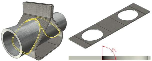
The operation enables users to build a cutout with a gap at a sheet body with the edges perpendicular to the main faces. Multiloop 3D profiles are supported.
There are three variants to create a cutout available in the command, switching between them is realized by icons.
|
Thickness |
|
Mid Plane |
|
Nearest |
A list helps you to determine which of the faces is to have a cutout: the nearest one or all having intersections in the given direction.
![]()
Command parameters
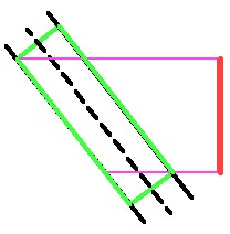
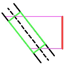
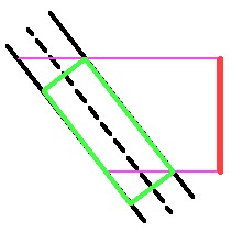
Type. Intersection of the projected profile onto a tilted sheet gives different results in terms of dimensions and position of the cutout depending on the surface to be considered the one for the profile to be projected onto. There are three variants for obtaining a cutout available:
●Thickness. Maximum cutout size.
●Mid Plane. According to the profile projection intersection with the middle surface of the sheet workpiece.
●Nearest. According to the profile projection intersection with the nearest surface of the sheet workpiece.
|
|
|
By thickness |
By middle |
By nearest |
Cutout. There are two variants:
●To Nearest. The cutout will be made in the given direction at the nearest to the profile surface of the workpiece only.
●Through All. The cutout will be made at all the surfaces of the workpiece that the profile projection intersects in the given direction.
Symmetric. Symmetric direction of the profile projection.
Gap. Sets the gap by equidistance from the cutout obtained.
Round Corners. Profile corners rounding.
The command menu options are:
|
<Ctrl+Enter> |
Finish input |
|
<P> |
Set entity Parameters |
|
<X> |
Exit command |
|
<F5> |
Preview Operation Result |
|
<B> |
Select Body |
|
<F> |
Draw Profile |
|
<W> |
Select Contour |
|
<D> |
Select Direction |
Finish input. To build geometry according to the given parameters. In case the parameters are insufficient, the option in not available.
Set entity Parameters. Call a standard 3-D design command parameters dialog.
Exit command. Shuts down the command cancelling the given parameters.
Preview Operation Result. The option enables/disables a standard option for reviewing 3-D design commands.
Select Body. In case there are several bodies at the 3D scene, use this option to select the body where cutout will be made. The option is active by default in case there are several bodies at the 3D scene.
Draw Profile. The option enables you to build a profile in the transparent mode. You should choose a workpiece face and the system automatically switches over to drawing work plane mode. Then you build a closed outline within the face. The created profile will be selected automatically on exiting from the drawing on the work plane mode.
Select Contour. The option chooses a profile to create a cutout. You should choose a profile determining the cutout. The profile must be closed. The option is active by default in case there is only one body at the 3D scene
Select Direction. The option selects the profile projection direction. The direction is determined by a vector that can be set by a face or a plane (the plane sets a normal along which the projection direction vector is oriented).
Creating a cutout by normal
A typical procedure when working with Normal Cutout command:
●Choose a sheet body if there are several bodies at the 3D scene.
●Choose the profile determining cutout shape.
●Set the profile projection direction.
●Choose the cutout calculation type.
●Set the gap and other parameters if necessary.
●Finish entering.