Unbending


Unbending |
|
SMU: Unbend command is used to unbend the folds:
Icon |
Ribbon |
|---|---|
|
Sheet Metal → Unbend |
Keyboard |
Textual Menu |
<SMU> |
Operation > Sheet Metal > Unbend |
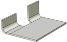
The operation enables users to “unfold” the part and obtain a workpiece model for the designed sheet part. It can be helpful for making a sheet part unfolding drawing.
The operation works not only with the bodies created in bending operations. “Unfolding” of imported bodies, cylindrical faces obtained by turning or extrusion is also possible. Several folds can be unbent at a time.
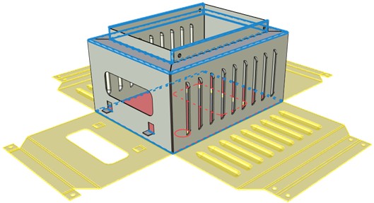
The folds to be unbent are chosen by selecting cylindrical faces. If you select a body and not separate unbending faces, the system automatically finds all the surfaces available for unbending and creates unfolding. If unbending variant offered by the system satisfies the user, the cylindrical faces to be unbent can stay unselected.
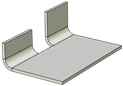
At the same time with the fold chosen, the ones coaxial with it can be unbent. Coaxial are the folds that meet the following conditions: they belong to one and the same body, have bending lines lying on one straight line, have the same radius, angle and direction of bend (relative to the workpiece).
|
|
|
|
|
Coaxial bends: one bending line, the same radius, angle and direction of bend relative to the workpiece |
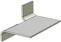
Not coaxial bends: different bending direction relative to the workpiece |
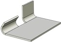
Not coaxial bends: different bending angles |
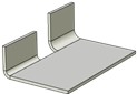
Not coaxial bends: different bending radii |
Not coaxial bends: different bending lines |
When unbending, the workpiece neutral layer coefficient is taken into account. If a part created without using sheet metal operations is unbent, the neutral layer coefficient is determined by the user in command parameters.
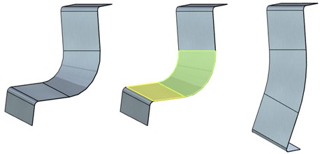
The part section that is to remain stationary when unbending is chosen automatically by the system. By default such a face is highlighted yellow at the 3D scene. If necessary, the stationary face can be selected manually, using an automenu option.
The unbending operation preserves all the topology obtained before, when creating the folds, i.e. the number of faces and edges of the body before and after unbending stays the same. It enables users to see bending areas at the flat unfolding and use them for example for future re-bending.
The operation enables users to unbend unclosed conical faces of a body.
Unbending cylindrical sheet bodies, truncated conical sheet bodies and random unfoldable surfaces is also available.
Operation parameters
NF. Unbend operation supports working with both the bodies created with the help of sheet metal commands and the bodies created in other ways. Therefore, unlike other sheet metal commands, there is a wider range of NF setting variants.
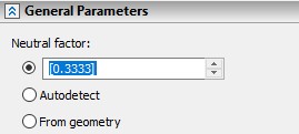
●User value. It is entered by the user in the upper field. In case of selecting the bodies created not with sheet metal operations, it is the default variant.
●Autodetect. Substitution from the table according to unbent body thickness and selected cylindrical face radius.
●From geometry. The option is for the bodies obtained in sheet metal operations for which Neutral factor is already set. In case of selecting the bodies created with sheet metal operations, it is the default variant.
All the faces involved in unbending are unbent with the same coefficient.
Reverse direction. The option is available for unbending closed body faces. It enables users to change unbending direction relative to the selected cutting plane.
Gap. The field is only active when unbending closed body faces. It enables users to set the gap by cut.
Unbend coaxial bends. It sets the forced unbending mode for the folds coaxial to the ones being selected in addition to them. The flag is on by default. When removing the flag only selected folds are unbent.
The command automenu options are:
|
<Ctrl+Enter> |
Finish input |
|
<P> |
Set entity Parameters |
|
<X> |
Exit command |
|
<F5> |
Preview Operation Result |
|
<A> |
Select operation |
|
<E> |
Select cylindrical bend face |
|
<K> |
Select immovable unbending face |
|
<S> |
Select node to define split surface |
|
<D> |
Select unbending direction |
|
<R> |
Cancel selection |
Finish input. To build geometry according to the given parameters. In case the parameters are insufficient, the option in not available.
Set entity Parameters. Calls a standard 3-D design command parameters dialog.
Exit command. Shuts down the command cancelling the given parameters.
Preview Operation Result. The option enables/disables a standard option for reviewing 3-D design commands.
Select operation. The option to select a body for the operation. It is active by default at calling the command. When selecting a body, the system itself searches for all the faces available for unbending and creates the body unfolding.
Select cylindrical bend face. Selects separate faces for unbending. You can choose cylindrical, conical and closed faces as well as other faces with unfolding.
Select immovable unbending face. Enables you to choose the stationary face manually. It is necessary when the stationary face selected automatically by the system does not satisfy the user.
Select node to define split surface. The option is only available when selecting a closed face. You need to select a 3D node which defines the position of the plane along which the body with the closed face will be cut.
Select unbending direction. The unbent face lies in the plane coinciding with the one tangent to the face being unbent in the point determining the cutting plane. The option enables you to define one of the two possible directions: to the right or to the left of the cutting plane. The direction vector projection onto the tangent line determines unbending direction. The direction vector can be specified by an edge or a plane (the plane determines the normal vector). You can also change unbending direction by setting the flag on/off in Reverse direction option.
Cancel Selection. Cancels selection of all the elements and clears the operands window.
Creating the operation
A typical procedure for creating the operation is as follows
●To select a body. The system offers an unfolding variant.
●To set the Neutral factor.
●To change the stationary face if necessary.
●Finish input.
If the result offered by the system automatically doesn’t satisfy the user, select bending faces manually.
●Select bending faces.
●Set the Neutral factor.
●Change the stationary face if necessary.
●Finish input.
If the surface is closed:
●Select bending face.
●Select the point determining the cutting plane position.
●Set the unbending direction if necessary.
●Set the Neutral factor and Gap.
●Finish input.