Custom Pipeline Ending Fragments |
  
|
The library of standard pipeline endings is supplied with T-FLEX CAD. You can use them in the ![]() Pipeline, Wire/Cable, Air Pipe command. If necessary, the library may be supplemented by custom fragments for any type of routings. When creating such fragments, follow the rules described below.
Pipeline, Wire/Cable, Air Pipe command. If necessary, the library may be supplemented by custom fragments for any type of routings. When creating such fragments, follow the rules described below.
In the fragment file you must create the following external variables and use them for defining corresponding geometrical parameters:
•Diameter or D - pipe diameter (permissible values range from 0 to 10000)
•Thickness or T - pipe wall thickness (permissible values range from 0 to 10000)-
•InnerDiameter or InnerD – flag for usage of internal diameter (possible values 0 or 1)
Variable InnerDiameter (InnerD) can be used for the suppression of one of the bodies in the fragment file. One body will be visible when using internal diameter, another - using external.
After creating 3D model, you should do the following:
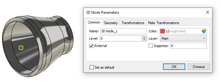
•Create external 3D node (there must be only one external node). This node will limit the adjoining pipe. It should be placed on the "inner end" of fragment body.

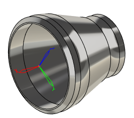
•Create external LCS. This LCS should be placed on the "outer end" of fragment body. It will be used for fixing the fragment. It must be assigned as a primary fixing LCS in the fragment's Document Parameters.


More information on how to create LCS can be found in the Local Coordinate Systems chapter.
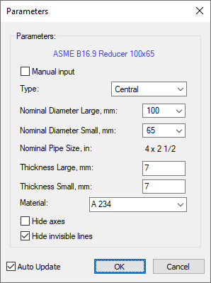
•Create custom external variables dialog (optional step). This dialog is automatically embedded in the parameters window when you call editing of ending variables in the command of pipeline creation/editing.
Learn how to create a dialog in the Controls chapter.

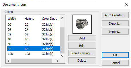
•Create icon using the Icon command (optional step).

•In the variable editor add diagnostics for invalid combinations of fragment's external variables values.
•Save the fragment document.
•Add the fragment into the standard pipeline segments library using the following automenu option of the ![]() Pipeline, Wire/Cable, Air Pipe command
Pipeline, Wire/Cable, Air Pipe command