Create 3D Fragment |
  
|
Calling the command:
Icon |
Ribbon |
|---|---|
|
Assembly (3D) > Assembly > Create 3D Fragment |
Keyboard |
Textual Menu |
<FM> |
File > Fragment > Create 3D Fragment |
It allows to create a new document from one of the prototypes available in the system and insert such document into the current one as a 3D fragment. The inserted fragment can then be opened in context of assembly. Thus you can design an assembly using the "Top-down" method.
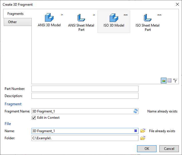
In the command's dialog, you should specify a desired prototype and press OK. The initial content and parameters of the resulting document coincide with content and parameters of the prototype. When opening the created document for the first time outside context of assembly, the system opens a window of the document with the same set of view windows and same tab of the ribbon, that were open at the moment of saving the selected prototype.
The list of prototypes available in the upper section of the dialog is common for several commands. Changes made in one of the commands affect the content of the list in others. Information on editing the list can be found in the description of the ![]() Save as Prototype command.
Save as Prototype command.
Only two tabs of the list are displayed in the ![]() Create 3D Fragment command: Fragments and Others, where the content of the first one is filtered in order to exclude drawing prototypes.
Create 3D Fragment command: Fragments and Others, where the content of the first one is filtered in order to exclude drawing prototypes.
Additionally, you may specify following parameters in the lower section of the dialog:
•Part Number and Description
Content of these input boxes will be recorded in eponymous columns of resulting document's product composition. If Part Number and Description are specified in product composition of a prototype, these boxes will be filled automatically, upon selecting such prototype. You may edit auto-filled values, if necessary. In order to restore an auto-filled value use the ![]() Update by Selected Prototype button at right side of an input box.
Update by Selected Prototype button at right side of an input box.
•Fragment Name
The name of the fragment insertion operation in the current assembly. If Fragment Name is filled in document parameters of the selected prototype, it will be put into this box automatically. You may still edit it manually. In order to restore the name inherited from prototype, use the ![]() Update by Selected Prototype button at right side of an input box.
Update by Selected Prototype button at right side of an input box.
•Edit in Context
If the checkbox is enabled, the fragment will be opened in context of the current assembly upon creation.
•Name
Name of the resulting document's file. If Part Number and/or Description are filled (see above), the default name is generated automatically using them. You may edit auto-generated name, if necessary. In order to restore an auto-generated name use the ![]() Update by Selected Prototype button at right side of an input box. The format of auto-generated name can be customized using the
Update by Selected Prototype button at right side of an input box. The format of auto-generated name can be customized using the ![]() Naming rule button at the right side of the input box. The button invokes the following dialog:
Naming rule button at the right side of the input box. The button invokes the following dialog:
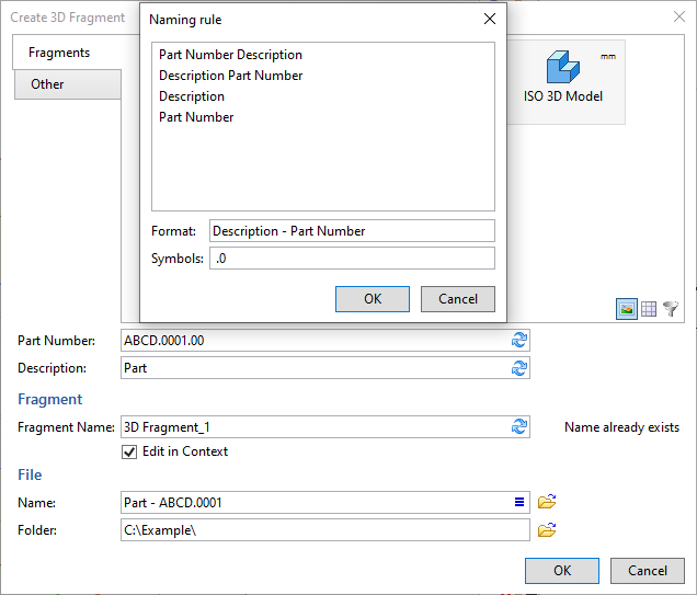
In the list in the upper section of the dialog, you can select one of the options defining the order of using Part Number and/or Description in auto-generated name.
In the Format input box, you can supplement the selected option by adding symbols before, after or between Part Number and/or Description.
In the Symbols input box you can specify symbols to be omitted from the end of the resulting name.
The example of the naming rule usage is shown in the picture above.
The ![]() Select button located to the right of the Name input box invokes the standard file selection dialog, where you can select an existing file to be replaced by the resulting one. Upon selecting a file, Name and Folder input boxes get filled automatically, and the "File already exists" notice appears to the right of the Name input box.
Select button located to the right of the Name input box invokes the standard file selection dialog, where you can select an existing file to be replaced by the resulting one. Upon selecting a file, Name and Folder input boxes get filled automatically, and the "File already exists" notice appears to the right of the Name input box.
If you leave the Name box empty, the name of the resulting document will be generated by adding an index number to the name of the selected prototype. Index numbers are counted from 1 for all documents created from this prototype within the current T-FLEX CAD session.
•Folder
Path to the resulting file. The ![]() Select button located to the right of the input box invokes the standard folder selection dialog. In case of using the folder selection dialog, the Folder box gets filled automatically in accordance with the location of the selected folder. In case of inputting a path via keyboard, the "Incorrect path" notice appears to the right and the input box gets highlighted in red, if the specified path cannot be found.
Select button located to the right of the input box invokes the standard folder selection dialog. In case of using the folder selection dialog, the Folder box gets filled automatically in accordance with the location of the selected folder. In case of inputting a path via keyboard, the "Incorrect path" notice appears to the right and the input box gets highlighted in red, if the specified path cannot be found.
Example of using the command when working with Top-down assemblies
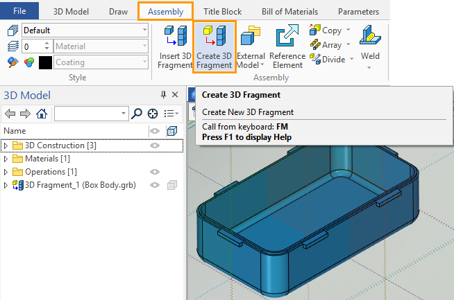
Create a Box Cover for Box Body. Go to the assembly file "Box" (creation of which is described in the previous section). Select the Create 3D Fragment command.
If you set the Edit in Context flag in the appeared dialog, then after saving the file to disk, the created fragment will be automatically opened in the context of the assembly. Then all the elements that are currently in the assembly will be available for constructions creation. In this case, only the geometry of the "Box Body" fragment will be available, because there are no other fragments in the assembly yet.
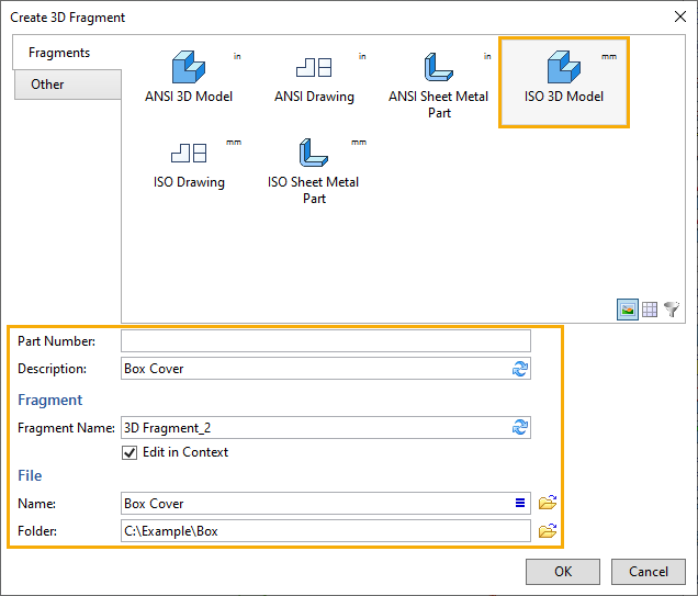
We want to set the relationship between Box Body and Box Cover: between the upper face of the body, its centering edge and the mate parts on the cover. This should be done using Reference Elements. You need to create Reference Elements in the context of the assembly – so specify the Edit in Context flag.
In the create fragment dialog specify the name of the file and select the prototype "3D Model".
In the "Fragment Name" field, change the default name to "3D Fragment_2", because in our case the box Cover fragment will be the second in the assembly. In General, the logic of naming fragments in the assembly is up to the user, because neither the formation of the assembly structure nor the structure of the part is affected by the name of the fragment.
Since the Edit in Context flag was specified, the assembly geometry will become semi-transparent, and a special panel will appear in the upper right corner of the 3D scene to control the main options of the fragment in the context of the assembly.
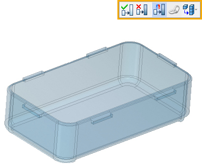
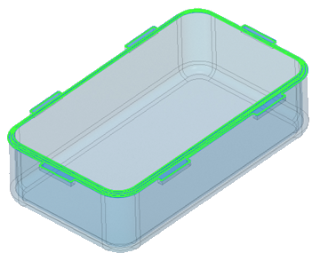
In the Ribbon, on the Assembly tab, select the Reference Element command (more information about this command can be found in the Reference Element subsection). Select two faces of Box Body: the top defines the centering edge of the body, the bottom – the surface on which the cover leans. In the command parameters window, you can see a list of faces. To expand the list of reference elements, click the icon next to the field indicating the number of reference elements.
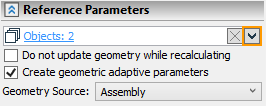
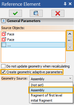
The Create geometric adaptive parameters option flag means that the created reference element will be placed in the geometric parameters of the fragment, and the edited fragment will become adaptive. Create Geometric adaptive parameters is only possible when specifying the source geometry in the assembly.
If the option flag Do not update geometry when recalculating is not set, the Reference Elements will be automatically updated when you recalculate the references from the Assembly Structure window.
Geometry Source - Assembly (for more information about variants, see the subsection Geometry Source). If a Reference Element is created between the assembly and the first level fragment (as in this case, because we specified Geometry Source: Assembly) the default reference will be the geometric parameter, and when recalculating the assembly will change the fragment without updating the Reference Elements, but only in the assembly. The geometry of the fragment inside its file will remain unchanged until the link is updated: manually or through the Assembly Structure window. You can learn more about the options for linking fragments to an assembly in the corresponding section below.
Click the icon ![]() to exit the fragment editing in the context of the assembly with saving the changes in the fragment file.
to exit the fragment editing in the context of the assembly with saving the changes in the fragment file.
It is important to pay attention to the Assembly Structure window. The fragment of the box cover is adaptive, because it has geometric parameters, the fragment of the body is non-adaptive, because it does not contain geometric parameters.
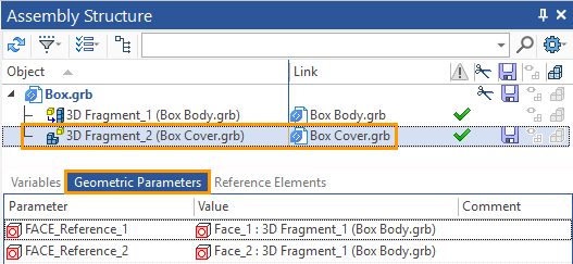
Further creation of the box Cover geometry can be carried out both in the context of the assembly and simply by opening the fragment file. On the basis of reference geometry, you need to use three-dimensional modeling commands to create a Box Cover geometry.

If you work with the fragment file in the context of the assembly, it is better to disable the Select Assembly Elements ![]() option. In this case you will not create links accidentally. After the completion of the constructions creation you should exit the context of an assembly by clicking the icon
option. In this case you will not create links accidentally. After the completion of the constructions creation you should exit the context of an assembly by clicking the icon ![]() .
.
If you create the fragment geometry outside the context of the assembly, you should update the assembly after you save the fragment file. When you open the assembly file, in the dialog that appears automatically when you edit and save the assembly fragments, you must specify the update of the assembly.
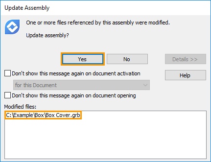
Now, to explain the work of Reference Elements and Geometric Parameters, let's change the geometry of the Box Body.
Open the fragment "Box Body". You can open a fragment in the context of an assembly or simply open the fragment file. Open the fragment in the context of the assembly. To do this, in the Assembly Structure window, call the fragment using ![]()
![]() . Change the length of the Box Body.
. Change the length of the Box Body.
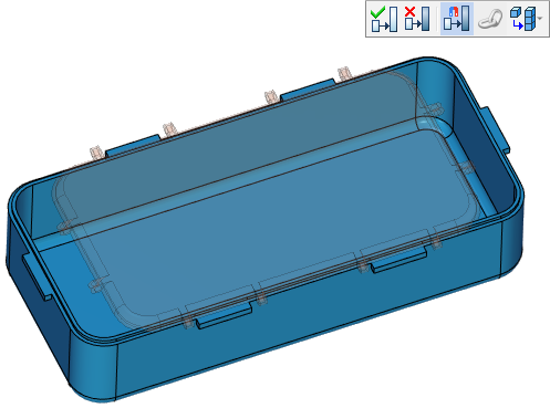
A fragment of Box Body has changed its length, Box Cover-did not, because the assembly does not know about the changes. Only after we leave the context ![]() the changes in the box Body fragment will be saved. After leaving the context, you are back in the Box assembly file. In the assembly file, the reference to the Box Body file is automatically updated,and the assembly will already have the modified body geometry. The Box Cover fragment automatically changed the geometry, and Box Cover corresponds exactly to the new geometry of the case: after we changed the length of the container body - the source geometry of the adaptive reference elements was rebuilt, and a new value was assigned to the geometric parameters of the box Cover fragment in the assembly.
the changes in the box Body fragment will be saved. After leaving the context, you are back in the Box assembly file. In the assembly file, the reference to the Box Body file is automatically updated,and the assembly will already have the modified body geometry. The Box Cover fragment automatically changed the geometry, and Box Cover corresponds exactly to the new geometry of the case: after we changed the length of the container body - the source geometry of the adaptive reference elements was rebuilt, and a new value was assigned to the geometric parameters of the box Cover fragment in the assembly.
Open the Box Cover file separately. In the Box Cover file, the geometry has not changed (if we open the cover fragment in the context of the assembly, its geometry in the assembly will be displayed, not the geometry in the source file). This behavior of the fragment is caused by the fact that its reference elements are geometric parameters, which means that the geometric parameters in the assembly will be set according to the values of the geometric parameters in the assembly, and in the source file geometric parameters will have the value before the changes. In this case, the Reference Element, which is a geometric parameter, behaves as an External Variable that can take a value in the assembly other than the value that takes in the source file.
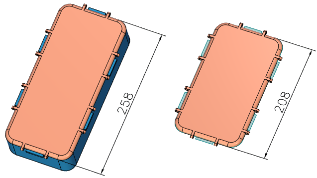
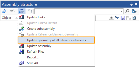
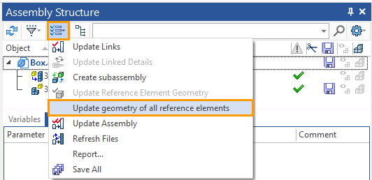
When creating Reference Elements, you did not specify the Do not update geometry when recalculating option flag - then you can update the Reference Elements through the Assembly Structure window. You can update all links, but only in a separate fragment. In this case, there is no difference, because only one fragment of the assembly contains reference elements.
Open the Box Cover fragment file again.
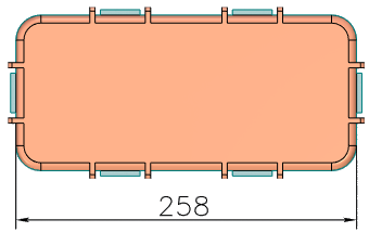
Reference Elements were updated (a new version of the source geometry was borrowed), the Box Cover geometry was automatically recalculated and saved.