Assigning Transformations to 3D Entities


Assigning Transformations to 3D Entities |
|
The command serves for translating, rotating, scaling and mirroring operations and 3D constructions. Transformation parameters are recorded in the properties of 3D elements. Moreover, properties of operation (or the element of 3D construction) can contain simultaneously several transformations that are executed successively one after another. It is also possible to form a group of objects and create common transformations for them.
To define transformation parameters of 3D elements, use the command “3EG: Transform Element”. However, a transformation can be specified directly in the parameters of specific elements as well.
Most common examples that involve transformations are assemblies of 3D fragments, the exploding mode and mates.
In T-FLEX CAD there are several types of transformations:
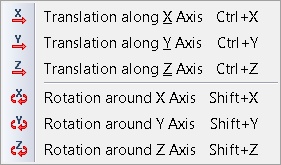
●Translation. This type of transformation allows us to specify translation with respect to the coordinate axes Х,Y,Z or in one of three coordinate planes along two axes simultaneously.
●Rotation around axis. This type of transformation allows us to specify rotation with respect to any coordinate axis. Transformation is specified with a value of the rotation angle.
●Scaling. This type of transformation allows us to change the size of the object with respect to the coordinate system or the point of scaling. The transformation is specified by the value of the scale.
●Symmetry. This type of transformation allows us to create the object symmetrically with respect to the selected plane. One of the planes of the coordinate system is used by default.
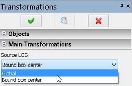
For transformations of operations and construction elements the Global coordinate system and the coordinate system at the center of parallelepiped encompassing the selected object can serve as an initial coordinate system. Direction of the axes of the coordinate system associated with the parallelepiped coincides with that of the Global coordinate system. For operations and construction elements the local coordinate system can be selected with respect to which the transformation will be performed.
|
|
|||||
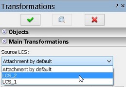
For transformations of fragments as an initial coordinate system we can use the default snapping (Global coordinate system), one of the external LCS of the fragment or the fragment’s LCS created during the fragment insertion (snapping by fragment). To select the target coordinate system of the transformation we use the option:
|
|
|||||
In case when it was not possible right away to orient LCS in a desired way, the functions of additional coordinate system specification can be employed. These functions allow us to quickly rotate the constructed LCS around its axes by 90°(![]() ,
,![]() ,
,![]() ), perform cyclic turning of the axes of the coordinate system around the origin (when pressing
), perform cyclic turning of the axes of the coordinate system around the origin (when pressing ![]() the axes change their places).
the axes change their places).
The target coordinate system can be defined in the process of specification of transformation. To do so, it is possible to use the option of selection of geometric snapping points for the center of the coordinate system of the element:
|
<N> |
Select point |
Directions of the axes in this case will be coincident with the global LCS.
In order to cancel all data that define the coordinate system at the present moment, the option of the automenu can be used:
|
<C> |
Cancel coordinate system for the current transformation |
For selection of the source coordinate system of the transformation we can use the option:
|
<S> |
Select or create source LCS |
After opening the new window at the beginning in addition to the standard options the following options are present in the automenu:
|
<1> |
Select 3D node or vertex as LCS origin |
|
<2> |
Select point that sets direction of the X-axis |
|
<3> |
Select point that sets direction of the Y-axis |
|
<C> |
Reset target LCS |
|
<A> |
Rotate LCS around the X-axis by 90° |
|
<O> |
Rotate LCS around the Y-axis by 90° |
|
<Z> |
Rotate LCS around the Z-axis by 90° |
|
<9> |
Change LCS axes orientation |
Selection of the ![]() option returns the user to the assembly and activates the mode of the target LCS specification.
option returns the user to the assembly and activates the mode of the target LCS specification.
Working with command
There are several ways to launch the «Transformation» command.
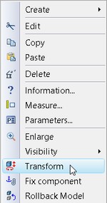
Firstly, the command can be called through the text menu of the program.
To invoke the «3EG: «Transformation» command we use:
Icon |
Ribbon |
|---|---|
|
Assembly → Additional → Move/Rotate |
Keyboard |
Textual Menu |
<3EG> |
Tools > Move/Rotate |
The «Transformation» command can also be invoked through the context menu of object.
After entering into the command, it is required to select 3D element for which the transformation will be specified. To do so, we use the option:
|
<1> |
Select objects for transformation |
|
<2> |
Select object for individual transformation |
Upon selection of ![]() it is possible to simultaneously select several objects for transformation. When
it is possible to simultaneously select several objects for transformation. When ![]() is selected it is possible to select only one object for transformation.
is selected it is possible to select only one object for transformation.
After selection of operation, construction element or fragment the program enters into the mode of specification of transformation for the selected object.
The properties window changes its view.
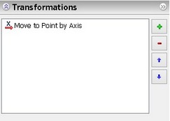
The «Transformations» section of the properties window can be used for control, correction of numeric values, creation and removal of transformations. In the special field the list of all transformations specified for the object at the present moment is displayed. Each transformation is marked with a special symbol that signifies its type (translation or rotation). If the value of transformation is specified with a constant, then the value of the constant is displayed next to the symbol. |
|
Below the main list of transformations there is a field for entry and editing of values.
To input the values of transformation, we can also use the special field on the system toolbar.
![]()
Graphics buttons are located to the right of the list of transformations. The After selection of the type in the list of transformations a new line will appear. In the values entry field the value of transformation can be entered. The transformations’ values can be specified both as numbers and with the help of variables and expressions. |
|
To save a transformation, press [Enter]. In addition, for specification of the value we can go to 3D window and use the dragger which moves according to the selected transformation type. At the moment of transformation creation its value will be displayed in the special field of the system toolbar:
●translation along one axis
![]()
●translation along several axes
![]()
●rotation
![]()
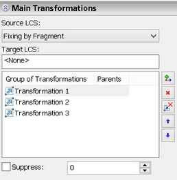
In the «Main transformations» section it is possible to create groups of transformations. Each group has its name. Below the list of transformation groups there is the «Suppress» flag. With the help of this parameter the transformation group can be temporarily excluded from the calculation. Next to the flag there is a field for entry of values. It is possible to use numeric values, real variables or expressions as a value for the given parameter. If the value different from 0 is entered into this field, the transformation group becomes suppressed. |
|
Graphics buttons are located to the right of the list of transformation groups. The buttons are accessible only if one object is selected.
With the help of the ![]() button it is possible to add a new group of transformations.
button it is possible to add a new group of transformations.
When pressing the ![]() button the last transformation group in the list is removed.
button the last transformation group in the list is removed.
The ![]() button allows us to remove all transformations groups.
button allows us to remove all transformations groups.
When pressing the ![]()
![]() buttons the order of execution of transformation groups changes.
buttons the order of execution of transformation groups changes.
Note that when changing the order of execution of transformations (including groups of transformations) the final result changes.
The «3D Assemblies. Creation of 3D models-assemblies» chapter describes the use of transformation groups in more detail.
The option of scaling is invoked with the help of the icon on the automenu toolbar:
|
<М> |
Scaling |
Scaling selected objects can be carried out in several ways.
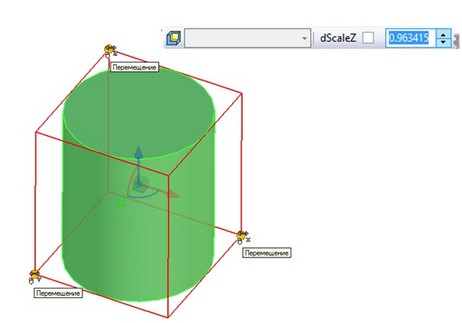
The first method implies the use of the encompassing parallelepiped that bounds the domain around the selected object in 3D window.
When pressing ![]() on one of the vertices of encompassing parallelepiped the axis (direction) along which the scaling of the object will be carried out is highlighted. After that the value of the scale can be specified in the special field of the system toolbar.
on one of the vertices of encompassing parallelepiped the axis (direction) along which the scaling of the object will be carried out is highlighted. After that the value of the scale can be specified in the special field of the system toolbar.
Several successive transformations of the scale are automatically summed up.
The second method implies the use of the «Scaling» tab in the properties window.
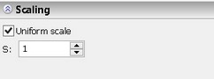
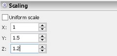
Scaling can be common (all values by all axes will be identical) and with different numeric values along the axes X, Y, Z.
The value of the common scale can be specified with the help of the «Uniform scale» flag
To specify different numeric values for each direction there is the entry field next to the axes.
To cancel the result of scaling we can use the option on the automenu toolbar:
|
<J> |
Remove scaling |
Scaling cannot be suppressed.
To create the symmetry of the selected object it is required to select the symmetry plane. To do so, we can use the option:
|
<P> |
Select mirror plane |
Planar faces, workplanes, 3D profiles and edges can serve as element with respect to which the symmetry will be applied.
To move element along or around the defined axis, use options:
|
<O> |
Rotate around arbitrary axis |
|
<B> |
Move along arbitrary axis |
Children of the transformed objects can’t be selected. This prevents recursion in the model.
Manipulator that specifies transformation appears after axis selection. You can specify transformation value in special field on the system toolbar.
To create transformations it is possible to use geometric attachments. The «Transformations» command works with the following nodes: vertices, edges, faces, 3D paths, profiles, 3D nodes and LCS.
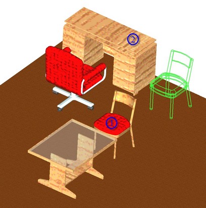
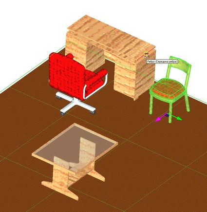
For example, let us suppose that in the existing 3D layout it is required to change location of the object (1) by aligning it with object (2).
Let us invoke the «Transformations» command via the context or text menu. We select the chair, object (1) for transformation. After that on the dragger we select the X-axis along which the translation will be carried out. Next, with the help of the cursor on the object (2) we select the midpoint of the edge to which the X-coordinate of the chair being moved will be «snapped». When pressing ![]() object (1) will move to a new location.
object (1) will move to a new location.
In the «Transformations» tab a new recording will appear.
If you need to transform an adaptive fragment you should enable the option Don’t use transformation for geometric parameters.
It is recommended to use the option if the geometry of the adaptive fragment does not depend on the adaptive parameters, but changes on their bases.
Group transformations
In the «Transformation» command it is possible to create transformations for several objects simultaneously.
Only the objects independent from each other can participate in the group transformation. Objects are considered independent if they are not connected with each other geometrically (i.e., they are not descendants of each other).
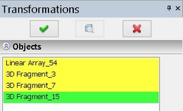
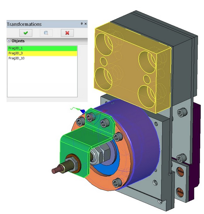
The selected objects are displayed in the «Objects» tab in the properties window.
To make selection of objects for transformation more convenient the command includes the following hot-key combinations:
●![]() − selection of object, ungrouping previous groups;
− selection of object, ungrouping previous groups;
●![]() +<Shift> − addition of object to the group;
+<Shift> − addition of object to the group;
●![]() +<Ctrl> − if the object is absent in the group add it to the group; if the object is already in the group delete it from the group.
+<Ctrl> − if the object is absent in the group add it to the group; if the object is already in the group delete it from the group.
Group transformation can be performed either in «common» coordinate system or in individual coordinate system of each member of the group.
After selection of objects for transformation the mode of specification of transformations in «common» coordinate system is enabled by default.
|
<G> |
Mode of setting transformations for selected objects in general coordinate system |
For a group transformation on the «Objects» tab and in the 3D window domain the object in the coordinate system of which the transformation is performed is highlighted with green color. All other members of the group are highlighted with yellow color.
If the mode of specification of transformations for selected objects in the «common» coordinate system is disabled the group transformation is transferred to the individual coordinate systems of each member of the group. The Global coordinate system or LCS of the fragment will serve as individual coordinate system for fragments. The Global coordinate system or the coordinate system at the center of the parallelepiped encompassing the selected object will be the individual coordinate system for operations and construction elements.
When selecting one object or a group of objects the command is launched in the mode of not allowing addition of new objects. When destroying the group, each object of the group is assigned the local transformation from the group transformation.
Group transformations can be used in the most efficient way in the mode of disassembly. More detailed information on using group transformations in the disassembly mode can be found in the «3D Assemblies Creation – Additional tools for working with 3D models-assemblies» chapter.
Using draggers
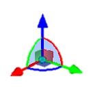
To specify parameters of transformation in 3D window the draggers can be used. A dragger constitutes an image of the coordinate system.
To change parameters of transformation with the help of a dragger, it is required to place the cursor over the dragger and move it to a new place. 3D element will also change its position together with a dragger.
Various parts of dragger are the active elements used for specifying transformations: ●the dragger axes are intended for defining translations; ●the dragger arcs are used for defining rotations; ●images of the planes are designed for translation in the planes XY, XZ, YZ; ●the dragger center is used for manual entry into the mode of dynamic snapping. Upon bringing the cursor to different active parts of the dragger the cursor changes its appearance prompting the user to specify the corresponding types of additional transformations. Next to cursor a tooltip will appear providing information about the type of offered transformation. The selected element of the dragger is highlighted with a different color. When a user points at the axis he can start to specify translation along the selected axis. Upon pointing at the arc, the system prompts the user to specify rotation in the corresponding plane. In addition, the axis of the dragger closest to the cursor is also selected so that a user could define a rotation by directing the selected axis towards a specific element of the model. When pointing at the image of the coordinate plane the user can start defining the shift in the selected plane. When selecting one of the dragger’s elements mentioned above the following commands become available in the context menu: - for translation along the axis; - for translation in the plane; - for rotation about three axes; - for translation along three axes. To specify transformation with the help of the dragger the user has to choose an active element of the dragger by pressing the mouse. |
|
Draggers are described in more detail in the «3D Assemblies. Creation of 3D models-assemblies» chapter.