3D View Parameters


3D View Parameters |
|
Defining All 3D View Parameters in One Dialog
Use the convenient dialog of the 3D view parameters for quick setup of the 3D window, when you need to change its several characteristics simultaneously (for example, the visualization method, the orientation, the view direction and the method of projecting from the system camera, etc.). Some of the 3D view parameters (for example, the background color, the parameters of light sources on the camera) can be defined only in this style dialog.
To call the dialog of the 3D view parameters, use the command "3VP: Set View Parameters":
Icon |
Ribbon |
|---|---|
|
View → Properties |
Keyboard |
Textual Menu |
<PW> |
View > Clip plane > Properties |
After calling the command, a dialog window appears, which contains all current 3D view parameters.
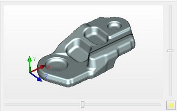
The 3D window contents preview pane is on the left-hand side of the dialog window. It displays all the same as in the master 3D window, but smaller. You can work with the image in the preview pane in the same way as with the image in the 3D view window: spin, pan, zoom. To quickly view the contents of the 3D scene, you can use the [View All] button - clicking it scales the image in such a way that all contents of the 3D scene are visible. All manipulations made in the preview pane will be also applied to the image in the 3D view window (after closing its parameters dialog).
The size of the 3D view properties dialog can be increased by moving the window boundaries with the cursor of the mouse when ![]() is being pressed.
is being pressed.
The "Show Coordinate System" flag can be used for disabling the coordinate system display in the 3D view window. The displayed size of the global coordinate system in the 3D window is defined in the command "SO: Set System Options" (the "3D" tab).
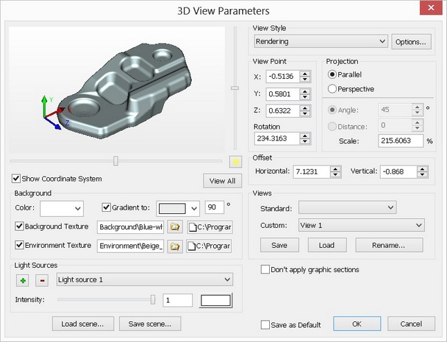
The "Background" group of parameters defines the background color of the 3D view window. To achieve a smooth transition of colors, set the "Gradient to" flag and specify two colors by selecting from drop-down lists. Clear the flag in order to make the 3D view window background monochrome. In such a case, specify just one color (the "Background color").
The “Use background texture” flag is used to enable/disable the mode of using the texture as a background of the 3D view window. When the flag is disabled the 3D view window has the color that is specified in the background parameters.
The “Use environment texture” flag is used to enable/disable the mode of using the texture as environment for 3D model. When the flag is disabled the specified texture will be suppressed.
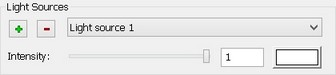
The group of parameters in the lower-left corner of the dialog window is provided to manage light sources attached to the active camera in the 3D scene. This group includes the list of dynamic light sources existing in the current 3D window, buttons for adding/deleting light sources attached to the camera, as well as control elements for defining parameters of each of the light sources.
To edit parameters of an existing light source, select this source in the drop-down list. Control elements located below the list allow changing the brightness of the selected light source (using the slider or numerically), as well as its color. The selected light source can be deleted by clicking the button The position of the selected light source with respect to the camera is defined using sliders located at the right and below the viewing pane of the 3D window contents. By default, dynamic light sources are placed directly on the camera (the sliders being positioned in the middle of their respective scales). By moving the sliders away from the center of the scale, one can move light sources right/left and up/down with respect to the camera. The |
|
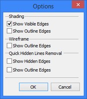
The method of the 3D scene rendering in this 3D window is defined using the "View Style" group of parameters. The drop-down list lets you select the desired method, while the ![]() button serves for defining additional parameters of each mode. Clicking this button brings up the "Options" dialog, which specifies the requirements on drawing various lines of the 3D model - edges, outline (silhouette), hidden lines - for each visualization method. The "View point", "Projection" and "Offset" groups of parameters define the view direction and the method of projecting from the system camera, as well as its distance from the center of the 3D scene. In the parallel projecting method, the camera distance is defined by the "Scale" parameter. This parameter defines the degree of zooming on the image in the 3D scene.
button serves for defining additional parameters of each mode. Clicking this button brings up the "Options" dialog, which specifies the requirements on drawing various lines of the 3D model - edges, outline (silhouette), hidden lines - for each visualization method. The "View point", "Projection" and "Offset" groups of parameters define the view direction and the method of projecting from the system camera, as well as its distance from the center of the 3D scene. In the parallel projecting method, the camera distance is defined by the "Scale" parameter. This parameter defines the degree of zooming on the image in the 3D scene.
The “Show Shades” flag is accessible only in case of another flag – “Enable Shades” from OpenGL settings of “3D” tab in “SO: Set System Options” command – is switched on. In addition the graphic board of your computer must support this functionality.
In the perspective projection, the camera distance can be defined either by the field of view angle of the 3D scene, or directly by the distance between the camera and the center of the 3D scene. All three parameters are defined numerically. Additionally, the scale and the field of view angle can be controlled using the mouse, directly in the preview pane of this dialog, similar to the way it is done in the 3D window itself when moving/rotating the camera. The "Offset" parameter defines the horizontal and vertical shift of the 3D scene center with respect to the camera.
The "Views" group of parameters, located in the lower-right corner of the dialog, serves for quick setup of the 3D window state. The "Standard" drop-down list lets you changing the view direction of the system camera according to one of the engineering drafting standards (for example, Front (elevation) View, Back View, Left (side) View, etc.). For this, simply select the desired scene orientation in the list. The "Custom" drop-down list serves for handling 3D views preset in the system.
A 3D view can be loaded (that is, the 3D window set up according to the information stored in the 3D view), saved (by writing 3D View information about the current state of the 3D window) and renamed (by simply changing the name, under which the given set of information is stored in the system). To load a 3D view, select this 3D view in the list and click the [Load] button. Clicking the [Save] button writes information about the current state of the 3D window in the 3D View selected in the "Custom" list. Clicking the [Rename…] button calls an additional dialog for defining a new name for the selected 3D view.