General Information


General Information |
|
What is three-dimensional assembly?
A three-dimensional assembly in T-FLEX CAD is a model that incorporates geometry of other 3D models stored in separate files. An assembly component can be a 3D model created in T-FLEX CAD, or a model from another system imported in T-FLEX CAD in one of the supported data exchange formats. To be clear, the engineer may think of an assembly (by its definition) as a model built from elements-operations within one document, rather than composed of separate part files. T-FLEX CAD does support such functionality. However, we will not call such document an assembly, since it does not refer to geometry taken from other documents.
An assembly document always maintains relations with assembly element (part) documents. As you work with an assembly, the system constantly tracks the state of the involved files. In the event of changes in an assembly component file, the system queries the user for updating the data. Each updated component will be regenerated and reloaded into the assembly. An assembly cannot be used without its components, while the each file involved in the assembly can be a fully independent document and, in turn, be an assembly itself. The number of nested levels of subassemblies is unlimited in the system.
 pu
pu
Use of parametric models
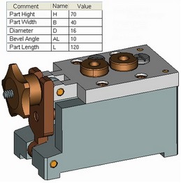
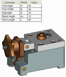
Any model in T-FLEX CAD can be built in such a way, that it can be modified by using external variables. Using such a model as an assembly component brings significant benefits. This is particularly effective, when such model is entered multiple times in one or several assemblies with different sets of external variable values. The same parametric part file can serve several assemblies at once. Parametric components of the assembly can be managed from within the assembly document.
Creating BOMs
Each assembly component may contain data within for automatic creation of various kinds of reports and Bills of Materials (BOMs). However, this chapter will not concentrate on creating BOMs. Detailed information on this topic can be found in the chapter "Bill of Materials".
Body intersection check
One of the typical tasks that require creation of an assembly is checking the model for assembling compatibility, checking all bodies of the assembly against mutual penetrations. T-FLEX CAD provides special tools for solving such tasks. You can start checking two selected bodies or all bodies in the model for intersections, using such tools. You can also measure particular geometrical elements or relations. For detailed information on this topic, refer to the chapter "Geometry Analysis".
Assembly design techniques
There are two main techniques to creating an assembly distinguished by the way of creating their components.
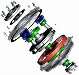
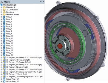
In many cases, it is convenient to take an already prepared model and insert it in the assembly by defining its position in the assembly. This assembly design technique is conventionally called "bottom up". In this framework, the components of a T-FLEX assembly are called 3D fragments. This approach is convenient for designing complex assemblies or standardized mechanisms made to large extent of standard parts. The inherent advantages of this approach are as follows.
●Designing parts in a separate file allows simplifying and subdividing the overall design process of a complex product.
●The same 3D fragments are available for reuse in different assemblies and for including into libraries of frequently used parametric 3D fragments.
●3D fragments can be created with the provision for automatic positioning in the space based on 2D fragments and the workplane (so-called "layout").
Nevertheless, it is often easier and clearer to design a part once you have the idea about its position in the assembly, and its size, based on geometrical elements of other parts in the assembly. We will call this design technique "top-down", while the assembly components, whose geometrical base is within that same assembly - Parts. An assembly model can be created "from scratch", as the engineer defines the general layout of the assembly unit. In the next step, separate elements are identified and refined, either in separate files or in the assembly context. This approach in some cases simplifies defining element attachments to each other, providing parametric relations between those. Use of the "top-down" technique sometimes allows avoiding use of external variables. The part parameters in this case are defined by references. Changes at low levels of the hierarchy of the related parts trigger automatic adjustment of all child parts in the assembly. Besides, the values of the original parameters of the model can be derived directly from the assembly context, based on the reference elements. For example, one can make holes in the cap based on the holes in the body. In this way, the engineer deals with elements belonging to the fragments, while seeing the part surroundings and having access to elements belonging to the assembly. This mode will further be referred to as working in the assembly mode.
The inherent difference in the two approaches does not prohibit combining both when creating assembly documents.