Document Management


Document Management |
|
Creating New Document
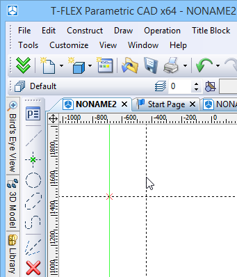
For creating new documents the dialog box “Start Page” can be used (see the chapter “Getting Started”). This dialog box is always present on the screen when the standard settings of the system are used. This dialog box enables to create new documents on the basis of the templates and also open already existing documents from the list of recently used ones. In addition to the dialog box “Start Page”, the commands grouped in the textual menu “File” can also be used for creating new documents.
To create a new drawing, use the command "FN: Create New Model":
Icon |
Ribbon |
|---|---|
|
Get started→ Files → Drawing |
Keyboard |
Textual Menu |
<FN>, <Ctrl><N> |
File > New > Drawing |
A command F3: Create New 3D Model allows to create a 3D model:
Icon |
Ribbon |
|---|---|
|
Get started→ Files →3D Model |
Keyboard |
Textual Menu |
<F3> |
File > New > 3D Model |
To create a new assembly drawing, use the command:
Icon |
Ribbon |
|---|---|
|
Get started→ Files → Assembly Drawing |
Keyboard |
Textual Menu |
|
File > New > Assembly Drawing |
To create a new 3D assembly, use the command:
Icon |
Ribbon |
|---|---|
|
Get started→ Files →3D Assembly |
Keyboard |
Textual Menu |
|
File > New > 3D Assembly |
Product structures of assembly documents include records for an assembly forming. It’s their only differ from the standard documents.
A created document name depends on the document prototype. Forstly created drawing will be called “Drawing 1”, firstly created detail – “Detail 1”. You can assign any other name upon saving the document.
T-FLEX CAD does not distinguish between the 2D drawing and 3D drawing files. In the document created as a 2D drawing, the 3D model can be generated afterwards. In the document created with the use of the command F3: Create new 3D model the new 2D drawings could be generated.
To create new documents, template files are used that are defined in the command Customize > Settings…, the tab “Files”. They contain elements and settings for the new document.
You can change prototype manually by editing of the respective template file or enter another template file name.
The prototype files should be placed in the folder “…T-FLEX CAD\PROGRAM\Template”. The name of the directory for the template files is set in the command Customize > Options…, the tab “Folders”.
A user on his own can create an arbitrary number of prototype files.
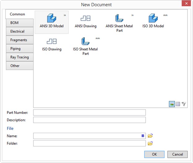
A new file can be created from an existing prototype using the option “New document” of the dialog box “Start Page”. Otherwise, use a similar dialog “New From...” by calling the command FP: Create New Document Based on Prototype.
Opening Document
A T-FLEX CAD document can be opened using the command "O: Open Model". Call the command using:
Icon |
Ribbon |
|---|---|
|
Get started→ Files → Open |
Keyboard |
Textual Menu |
<O>, <Ctrl> + <O> |
File > Open |
The new window Open will appear on the screen. This is a standard Windows dialog box for opening application files.
The command allows you to open not only *.grb format files, but also open files in formats of other systems.

When you open the file of another system format, you can select the Open or Open with parameters option.

If you select Open with parameters, a dialog similar to the import dialog for the specified format opens. In this way, you can open the model with the specified parameters.
More details about export can be found in the "Exporting And Importing Documents" chapter.
Panning and zooming in Active Drawing Window
The drawing image can be panned and zoomed in and out in the active drawing window. Zooming effectively changes the size of the working window of the drawing. The easiest way to do these manipulations is using a mouse with a middle wheel. Alternatively, the working window size can be changed by using the rulers as described below. Besides, a command is provided for this purpose, "ZW: Zoom Window". Call the command via:
Icon |
Ribbon |
|---|---|
|
View → Scale → Zoom Area |
Keyboard |
Textual Menu |
<ZW>, <F3> |
View > Scale > Zoom Area |
The following options are provided with the command:
![]() <P> Set command options
<P> Set command options
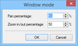
Selecting this option brings up a dialog box on screen with the following parameters:
Pan percentage. Defines the percentage of the working window shifting left/right and up/down.
Zoom in/out percentage. Defines the percentage of the working window magnification.
![]() <A> Zoom Model to paper size
<A> Zoom Model to paper size
This option redraws the working window according to the drawing format size. The latter is set in the command "ST: Set Document Parameters".
![]() <M> Zoom Limits
<M> Zoom Limits
This option calls the command "ZM: Zoom Limits" that fits the full image to the drawing area.
![]() <T> Actual Size
<T> Actual Size
This option calls the command “ZТ: Actual Size” the drawing and 3D model in accordance with their real dimensions.
![]() <I> Zoom In
<I> Zoom In
![]() <O> Zoom Out
<O> Zoom Out
These options respectively magnify and shrink the drawing image each time by a fixed percentage ratio specified in the command parameters.
![]() <L> Pan Left
<L> Pan Left
![]() <R> Pan Right
<R> Pan Right
![]() <U> Pan Up
<U> Pan Up
![]() <D> Pan Down
<D> Pan Down
These options move the drawing image by a fixed percentage ratio specified in the command parameters.
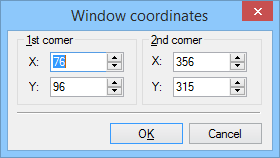
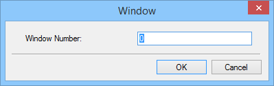
![]() <W> Set absolute window coordinates Calling this option brings a dialog box on screen for inputting window coordinates. The user can type in the coordinates of the two opposite corners of the working window.
<W> Set absolute window coordinates Calling this option brings a dialog box on screen for inputting window coordinates. The user can type in the coordinates of the two opposite corners of the working window.
![]() <BackSpace> Set previous window coordinates
<BackSpace> Set previous window coordinates
This option resets the active drawing window coordinates to the previous settings.
![]() <S> Save current window coordinates
<S> Save current window coordinates
This option allows saving the working window coordinates and assigning an Id to the saved configuration. A dialog box appears on screen for entering an Id from 0 to 9 to be assigned to the saved window configuration. To return to a saved window, type the number key of the desired Id (<1>, ...).
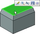
![]() Set the working window size by dragging selection box
Set the working window size by dragging selection box
An arbitrary area of the drawing can be zoomed on by specifying two opposite corners of a box. Move the cursor to one corner of the area to be zoomed on, and press and hold ![]() . A rectangle starts rubberbanding after the cursor. Drag it, selecting the desired area by box, and then release the button
. A rectangle starts rubberbanding after the cursor. Drag it, selecting the desired area by box, and then release the button ![]() . The selected area will be displayed zoomed on. A one-time call to any option of the "ZW: Zoom Window" command can be done asynchronously from within any element creation or editing command by typing <F3> function key or selecting the
. The selected area will be displayed zoomed on. A one-time call to any option of the "ZW: Zoom Window" command can be done asynchronously from within any element creation or editing command by typing <F3> function key or selecting the ![]() icon.
icon.
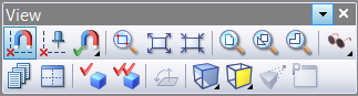
The options of the "ZW: Zoom Window" command are also accessible via the "View|Scale" menu and the "View" toolbar.
![]()
Toolbars

A toolbar is a set of icon buttons for calling the application commands. There can be several toolbars on screen simultaneously.
In the standard package of the T-FLEX CAD there are five toolbars: “Main toolbar”, “System toolbar”, “View”, “Full screen mode”, “Context” (toolbar which appears when entering fragment editing mode in the assembly context). In addition to that, any number of user-defined toolbars can be created (via the command “SB: Show Toolbars”). With the help of the same command the structure of user-defined and several standard toolbars can be modified as well (for example, of the toolbar “View”).
What toolbars to display is defined in the command "Customize|Customize…" on the "Toolbars" tab. Besides, a desired toolbar can be accessed via the context menu by pressing right mouse button while over any toolbar.
Any toolbar can be docked along any of the application window borders, or floating within. When floating, a toolbar window is titled, and can be resized.
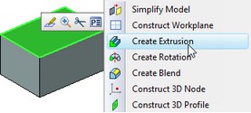
Embedded toolbars
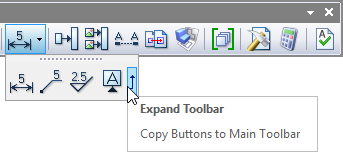
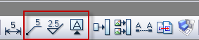
Several command pictograms in the instrument toolbars can be grouped on the principle of similarity of performed functions. In this case the instrument toolbar will show only one pictogram of the given group (the rest are not shown), and the button ![]() will be placed on the right side from the pictogram. By pressing this button the “embedded” toolbar with the rest of the pictograms of the given group will emerge.
will be placed on the right side from the pictogram. By pressing this button the “embedded” toolbar with the rest of the pictograms of the given group will emerge.
The embedded toolbar can be converted into the ordinary instrument toolbar. To do that, it is necessary to place the cursor on the header of the embedded toolbar, press ![]() and, without releasing the mouse, drag the toolbar to any place of the T-FLEX CAD window.
and, without releasing the mouse, drag the toolbar to any place of the T-FLEX CAD window.
The buttons of the embedded toolbar can be placed directly on the main toolbar. To do that, it is sufficient to press the button ![]() on the right end of the embedded toolbar.
on the right end of the embedded toolbar.
|
|
Bird's eye view window
Using Library Explorer
The library explorer menu window can be used for opening documents for editing, along with the "O: Open Model" command. It comes up on starting the application and docks by the left border of the application window. It also can stay floating. The user can control visibility of the library explorer window via the textual menu item "Customize|Tool Windows|Library Explorer" or in the context menu on right mouse button click over any toolbar. The library explorer shows the content of the open libraries. It allows to select libraries, open documents for editing and insert documents into the current one as fragments or pictures. The library explorer window may have a preview pane at its bottom or right-hand side. This pane will display the preview image or the properties of the selected document. The library explorer window can have various different settings accessible by
|
|
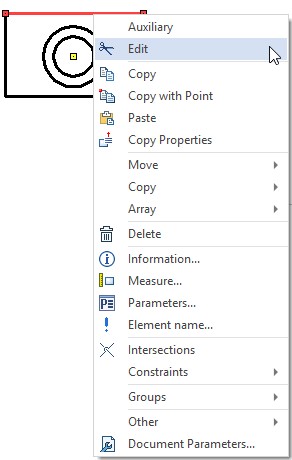
Context menu
Commands for working with elements in the Links window are available in the context menu.
Open file. Allows to open one or several selected files in T-FLEX CAD.
Open with. Allows to open the selected file with the help of an external application. The application can be selected from a coming up window.
Show in Folder. Opens Windows folders with the selected files.
Select file. Option allows to select the file which will replace one or several selected files.
For example, if the file name was changed and the file dissappeared from the assembly, you can select the renamed file using the Select file command.
Change link type allows to change one or several links types. For example, setting the type “Embedded” for an “External” link will put the external file, which is the link target, into the current T-FLEX CAD document, all data included, so that the file ceases being external.
An embedded link can be used for temporary storage of fragments data within an assembly document. For example, this is necessary when you need to move an assembly document to another computer. “External” link can be re-assigned afterwards to return back the external storage of fragments in the separate files.
Change Link command calls Change Link dialog window. You can change name, path or name and path for the link here.
The command can be used for multiple links. For example, if you change paths to several fragments, they will refer to files with the same name located in another directory.


If there are no files with desired name in the specified directory, a warning will be displayed in the diagnostics window.
Optimize path. All absolute paths will be replaced by relative path.
Rename/Move file. Allows to specify a new directory for fragment file storage and to rename the file. The file will be still associated with the current assembly.
Rename file. Allows to rename the fragment file associated with the link.
Update dublicates the ![]() option from the toolbar.
option from the toolbar.
A drop-down list with commands for working with the selected file is located in the bottom part of the context menu.
Additional columns appear in the window if integration with T-FLEX DOCs is enabled. These columns are used for team development.
Sorting and grouping are available for records of the Links window.
More information about sorting and grouping can be found in “Variables” chapter.
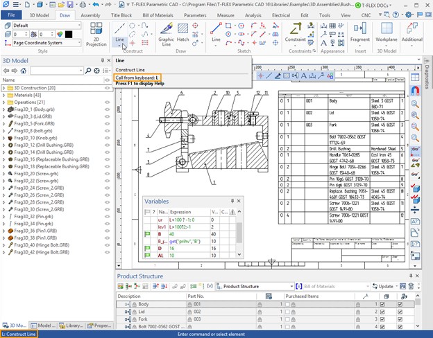
Automenu
Automenu is a special toolbar that contains icon buttons of the available command options. Automenu is context-sensitive. This means, its content changes depending on the current command and a state of the command. Two outcomes are possible when selecting an action-starting icon in the automenu. First – the result comes right after selecting the icon. For instance, selecting the parameters setting icon, ![]() , instantly brings up the parameter dialog box on screen. Second – the cursor changes the shape according to the selected option. To obtain the result, the user needs to move cursor to an appropriate location and press
, instantly brings up the parameter dialog box on screen. Second – the cursor changes the shape according to the selected option. To obtain the result, the user needs to move cursor to an appropriate location and press ![]() . For instance, selecting the construction line -
. For instance, selecting the construction line - ![]() - adds a line mark to the cursor. The cursor then should be moved to a line to be selected, and the button
- adds a line mark to the cursor. The cursor then should be moved to a line to be selected, and the button ![]() pressed. Only then, the construction line will be selected.
pressed. Only then, the construction line will be selected.
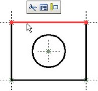
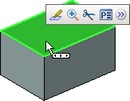
In the command anticipation mode, upon selecting elements with the help of The presence of the dynamic toolbar, while choosing 2D and 3D elements, depends on the settings of the command “SO: Set System Options”. For 3D elements the dynamic toolbar will be shown if the flag “Use Dynamic Toolbar” is turned on in the given command dialog box on the tab Dynamic Toolbar. In addition to that, while working with 2D elements, the parameter “Transparent Element Editing” has to be turned off. By default, the dynamic toolbar appears on the screen only for 3D elements. |
|
In addition to the icons of frequently used commands, the button ![]() for calling the list of additional commands will be shown in the dynamic toolbar. Upon calling a command from the additional list, the selected command is automatically transferred to the main set of buttons of the dynamic toolbar (for the elements of the given type). Modifications in the dynamic toolbar are retained in the current Environment of the system.
for calling the list of additional commands will be shown in the dynamic toolbar. Upon calling a command from the additional list, the selected command is automatically transferred to the main set of buttons of the dynamic toolbar (for the elements of the given type). Modifications in the dynamic toolbar are retained in the current Environment of the system.
|
|
|
To cancel changes in the set of buttons of the dynamic toolbar, it is possible to use command “Reset Command Usage” in the context menu of the dynamic toolbar.
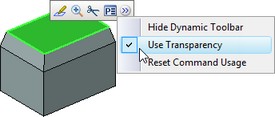
In the context menu of the dynamic toolbar, the flag “Use Transparency” is also available. When this flag is set on (for default settings), the toolbar looks semitransparent when it appears on the screen. The semitransparency diminishes as the cursor moves closer to the toolbar. When the flag “Use Transparency” is turned off, the toolbar is always displayed as nontransparent.