Before You Edit


Before You Edit |
|
This chapter gives basic ideas and recommendations on editing a 3D model and its related elements of a 2D drawing in T-FLEX CAD. By editing, we mean certain user actions aimed at making changes to an existing 3D model. There could be various reasons for editing:
1)correcting model flaws in the event of getting critical errors in the diagnostics window;
2)introducing improvements to existing model geometry, rearranging or rectifying a model, inserting sequences of operations in the middle of the model tree;
3)rearranging graphic elements in a drawing or in 2D constructions. Replacing elements. Resolving recursive references;
4)redefining geometrical or other properties of individual model elements;
5)modifying variable values;
6)modifying the model structure, reordering operations within the model tree;
7)modifying the methods of snapping and relations between 3D assembly elements, optimizing mates and setting up the function of a mechanism model;
8)deleting elements, excluding model objects from a sequence of related elements. Deleting sequences of related elements, deleting “extra” elements. Other.
A T-FLEX CAD model is usually a parametric one. Therefore, depending on a case it may become necessary to undertake a group of measures aimed at editing the model, since certain changes, once introduced, often cause a need to correct other relations. Therefore, before going ahead with profound editing, it is advisable to do some research and prepare the best plan of actions. When you do such preparations, you may face the following tasks:
1)identifying (researching) the model structure and the steps and methods of its creation;
2)identifying the sequence of related parents and children for a given model element;
3)finding elements:
●operations;
●3D construction elements;
●2D construction or graphic elements;
●variables that control the specific parameters;
4)tracing parametric dependencies: geometrical relations and element dependencies on variables;
5)geometry measurements and checks;
6)identifying invalid elements and the reasons behind model regeneration failures.
In this chapter we review the system tools that may be useful in various scenarios of the editing process. The specifics of editing certain elements is given in dedicated chapters of the documentation, which describe the workflow specifically for those elements.
We recommend to set aside a backup copy of the source file before proceeding with significant modifications to the model structure.
Before You Edit
Researching the Model Structure and Selecting Elements
The user may often face the task of understanding the sequence of the model creation, the order in which elements and operations are calculated, and identifying relations between model elements. In particular, you may face this task if you need to modify a model created by another author. The following model research approaches are possible:
●reviewing the model structure in the model tree window;
●using the rollback function to determine the sequence of operations creation and analyzing the methods used for creating operations at various steps of model creation;
●“Destructive method”. This implies sequential deletion of operations and detailed analysis of the model at certain creation steps, identification of individual operation creation methods, experimenting with the model in various ways at its early stage of creation. We recommend doing this kind of experiments with a copy of the source file;
●going into an operation editing mode, but then canceling the editing, in order to see what elements this operation was based on and how it was created. When you enter the editing mode, the time is spent solely to calculate the rollback state, and when it is canceled, the original state is quickly restored.
“3D Model” Window
The “3D Model” tool window serves to display the information about the 3D model structure and its creation history, as well as for selecting and managing the model elements. The 3D model tree displays all 3D construction entities and operations of the model. This information is displayed as a tree. One can select 3D elements either on the tree branches which illustrate the history of creating Bodies of the given a model, or on the auxiliary “Constructions” and “Operations” branches, where the elements are sorted by types.
The model structure can be traced by expanding the model tree branches and watching the order of operations creation. Each model tree branch represents the history of creating a certain Body of the model. Any element in the structure that possesses a creation history has an associated ![]() or
or ![]() glyph to expand or collapse the tree branch. Other elements have an associated
glyph to expand or collapse the tree branch. Other elements have an associated ![]() or
or ![]() glyph for viewing the list of source parent elements. Some elements do not have any associated glyph since they have neither parents nor a creation history within the model structure.
glyph for viewing the list of source parent elements. Some elements do not have any associated glyph since they have neither parents nor a creation history within the model structure.
By expanding the model tree branches one can watch the elements corresponding to a given operation, which were used as the base for the operation's creation. To view or edit the respective parameters, you can select the object by ![]()
![]() . The context menu containing the element's commands is displayed upon
. The context menu containing the element's commands is displayed upon ![]() .
.
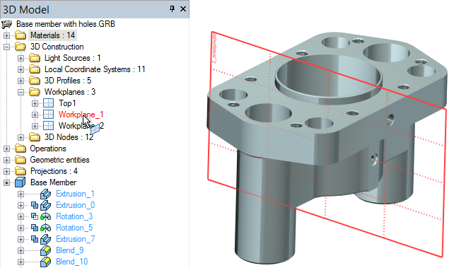
You can select 3D construction elements and operations in the 3D model tree within the folders containing the elements of the relevant type. Upon pointing the cursor to a 3D element name in the model tree, the respective element is highlighted in the 3D scene - this helps to keep the track of the location when there are many elements of the same type in the model. If you select ![]() an operation which is buried deep in the model structure, the system will attempt to highlight in the 3D window the model topology elements (edges, faces, vertices), which were created by this operation. This is possible only if such elements are still identifiable within the final Body. Such highlighting helps to understand what part of the model is represented by a given operation. By subsequently selecting operations in the model tree, one can understand the order and the purpose of the operations. This is how you proceed with the preliminary general analysis of the model structure.
an operation which is buried deep in the model structure, the system will attempt to highlight in the 3D window the model topology elements (edges, faces, vertices), which were created by this operation. This is possible only if such elements are still identifiable within the final Body. Such highlighting helps to understand what part of the model is represented by a given operation. By subsequently selecting operations in the model tree, one can understand the order and the purpose of the operations. This is how you proceed with the preliminary general analysis of the model structure.
To enable the selector and filter settings at the time of selecting elements in the 3D model tree, enable the “Use active View Filter” flag.
When analyzing the structure, it is helpful to know that the last operations in the creation history of the model's Body, that is the ones that are displayed in the 3D window, are by default entered in black in the model tree. Other operations are entered in blue. The names of the visible 3D construction elements are also entered in black in the 3D model tree. The invisible elements (that is, those hidden through the use of layers, the hide command or otherwise) are displayed in gray in the 3D model tree. When selected in the 3D model tree or simply pointed to with the cursor, the hidden 3D elements are highlighted in the 3D scene.
For detailed information on working with the “3D Model” window see the chapter “Basic 3D Terms and Concepts of Modeling with T-FLEX CAD 3D”.
Rollback Model
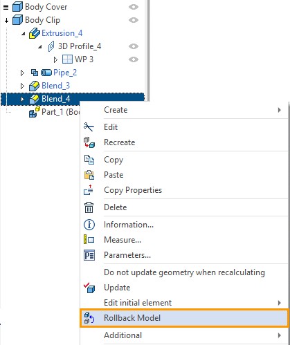
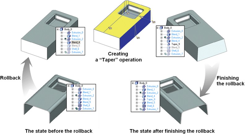
The system provides the function of rolling back a three-dimensional model to the level of a specified operation. This functionality is helpful in the cases when it is necessary to work more on the model somewhere in the middle of the model tree, that is, revert it to an earlier creation stage.
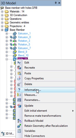
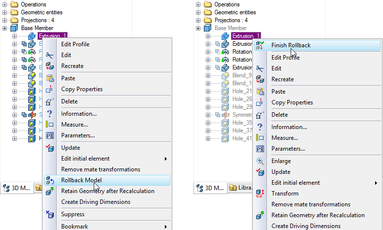
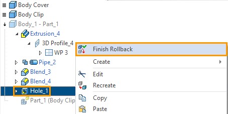
To perform a rollback, use the “3D Model” window. Select the operation, up to which you need to roll back. Click ![]() . Select the “Rollback Model” button in the context menu. To return from the rollback, select the “Finish Rollback” command in the context menu.
. Select the “Rollback Model” button in the context menu. To return from the rollback, select the “Finish Rollback” command in the context menu.
Elements and operations that follow after the rollback point in the model's history become hidden in this mode and are inaccessible for you to work on. In this state, those are marked by semitransparent icons in the model tree. All elements and operations newly created in the rollback mode are automatically inserted in the model's history. At each such instant, the system automatically rebuilds the relevant dependencies as necessary to be able to re-create the following operations. If for some reason the introduced changes result in errors in the model, then the system will offer restoring the model state before the rollback. This protects the user from introducing invalid modifications to the model.
Sometimes, it is helpful to subsequently delete elements and operations in order to get a detailed understanding of the model structure as part of other experiments. In this case, the system will not be spending time for saving and rebuilding relations, unlike in a rollback. But the model itself may be damaged by this, therefore this method should be used on a copy of the source file.
Tracing parameter dependences and relations between variables
One may often need to find out what elements directly depend on a given variable, or which geometrical or parametric relation makes the selected element interact with other objects in the model. This information is not reflected in the “3D Model” window.
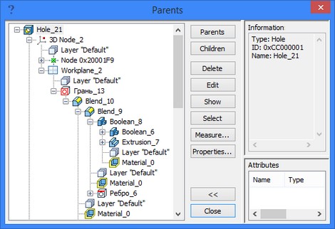
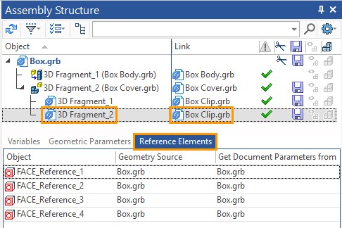
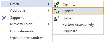
The “Help|Info” command brings up a special dialog window in which the full model structure is displayed that pertains to all model elements. Sequences of related elements are displayed as a tree. Unlike the “3D Model” window, the “Info” window's structure provides more details not only on the 3D elements, but also on the drawing elements and all auxiliary objects.
This command can be conveniently called from the context menu of the selected element of interest. In this case, the model structure in the command's window is given relative to the selected element or group of elements. The model structure can be displayed in two relational directions: Parents-Children or Children-Parents.
|
|
The command's dialog window provides the buttons for launching the general commands for editing, sorting elements and running measurements. Such commands are applied to the element selected in the model structure pane in the left-hand side of the dialog.
The "Info" pane in the right-hand side displays the data pertaining to the currently selected element. This includes its creation method, some general parameters, the ID, etc.
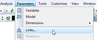
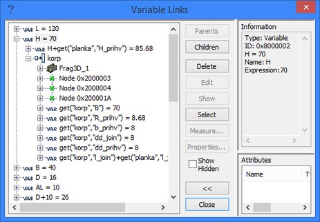
The special command “Parameters|Links…” serves to trace the elements which are directly controlled by each system variable or expression that involves that variable. This command's dialog window is similar to the window of the “Help|Information…” command. It displays all system variables and expressions, and the structural sequences of dependent elements relying on those variables and expressions.
|
|
Element Search
You can use the search to select an element, if you know its individual name or ID. To search an element, there is the dedicated command “Edit|Find…” You then need to enter the element ID or name in the command's dialog. To run the search, close the dialog by clicking the [OK] button. If the system finds the element, it will become selected and highlighted in the 3D window, and its name will be marked in the model tree. After that, you will be able to proceed with editing, as by calling a desired command or by accessing the context menu via ![]() .
.
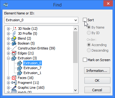
In the search window, all existing system elements are also arranged by types in the relevant folders. Selection can be done directly in the dialog window.
Selecting elements in the 3D scene
By default, you can only select the visible 3D elements in the 3D window. The elements hidden by whatever means - whether through the layers mechanism, or through suppressing or hiding 3D elements, etc. - are not selectable in the 3D scene.
If necessary, the user can enable selection of invisible elements in the 3D window (the "View" tab of the “ST: Set Document Parameters” command).
To select an object, point the cursor to it. The system will offer the current selection choice by highlighting the respective element and display a tooltip with the element name. To confirm the selection, click ![]() or
or ![]() . In the case of
. In the case of ![]() the context menu will appear with the set of the element's commands.
the context menu will appear with the set of the element's commands.
When selecting elements, pay attention to the selector's filter settings. To control 3D elements selection in a densely populated 3D scene, configure the selector (the command “FT: Set Selector Configuration”) and the filter (the command “FL: Filter Settings”). The filter quick access buttons are available on the system toolbar: ![]() . When all filters are enabled, then, upon pointing the cursor to a Body, the topology elements (faces, edges, vertices) are offered first.
. When all filters are enabled, then, upon pointing the cursor to a Body, the topology elements (faces, edges, vertices) are offered first.
The cursor may often point to several objects at once. In this case, if the system-offered selection choice is not suitable, then, after a 2-second delay, the multichoice cursor appears. It lets you make another choice by spinning the mouse wheel.
Operations Selection by Geometry Elements
You can select a topological element (face, edge, vertex) and enable edition of the operation, which created it. To do this, use the context menu.
|
|
There is a drop-down submenu for the last operation in the body model tree in the context menu of each topological element. The name of the string in the context menu corresponds to the name of the last body operation for which the submenu is formed. For example, the figure shows that when the context menu for the face formed by the operation “Extrusion_1” is called, the context menu shows the name of the last operation in the model tree of the body - “Blend_5”.
|
|
If you go to the submenu of the operation, you can call the command to edit it.
|
|
In the selector filter set on the system panel there is the![]() <Ctrl + Alt + J> Select operations by created faces option, which allows you to select earlier operations in the model history by topological elements. If you enable this option, the names of those operations that directly created the selected topological element will appear in the context menu.
<Ctrl + Alt + J> Select operations by created faces option, which allows you to select earlier operations in the model history by topological elements. If you enable this option, the names of those operations that directly created the selected topological element will appear in the context menu.
![]()
Let's make this option active. Call the context menu for the vertical face once again. It can be seen from the figure that when the option ![]() is active, the context menu does not indicate the name of the last operation in the body model tree (“Blend_5”), but the name of the operation that formed this face, i.e. - “Extrusion_1”.
is active, the context menu does not indicate the name of the last operation in the body model tree (“Blend_5”), but the name of the operation that formed this face, i.e. - “Extrusion_1”.
|
|
Similarly, with the active option ![]() , the system will work for other elements, for example, for the edges of the face formed by rounding.
, the system will work for other elements, for example, for the edges of the face formed by rounding.
|
|
|
|
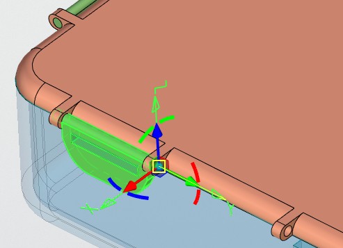
To quickly switch to editing any body operation, you can use the <Ctrl + Alt + J> Select operations by created faces option in conjunction with the <Ctrl + Alt + X> Select Operations filter.
![]()
Then, when you hover the cursor in the 3D scene on the edge of the body, the system will offer to select operations that participated in the creation or modification of this face. If the element forming operation is Primitives, Extrusion, or Sheet Metal, then control manipulators will be automatically available.
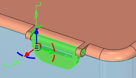
To edit other operations, you can use the Edit command available in the drop-down panel.
![]()
If the system finds several operations for a given face, the multivariate selection icon will appear at the cursor.
Geometry Measurements and Checks
The system has several different tools to perform various checks and measurements of geometrical data. This paragraph lists them all without providing a detailed account of the respective working techniques. For details please refer to the dedicated sections of the documentation.
●The “Parameters|Measure” command serves to get geometrical data about an object or to measure relations between two selected objects. This command operates mostly in the 3D window or in the drawing area where objects to be measured are selected. The achieved results can be bound to a variable. This function is used when you need to save the results of measurements and include the achieved data in other expressions that drive some model parameters. This command is also accessible via the context menu on right-clicking ![]() a geometrical object or from the context menu called from an input box in any of the dialogs.
a geometrical object or from the context menu called from an input box in any of the dialogs.
●The sets of commands in the “Tools|Geometry Analysis|…” group serves to perform various studies of the model, as getting mass-inertia properties of a selected body, the geometry validity check on various bodies, body intersection or contact analysis of the model, etc.
Sometimes, to perform a series of distance measurements between various elements of a part, it may be helpful to construct a temporary 2D projection somewhere on the 2D page and create the required dimensions. Once done with measurements, you can delete that projection unless useful for other purposes.