Editing Fragments


Editing Fragments |
|
Fragment editing can be performed in order to modify its parameters (references to file, image settings, the way it is included into the bill of materials, etc.), fixing, variables. In some cases in order to make changes, it is enough to turn to the dialog of the element parameters. Sometimes it is convenient to use the fragment-editing command “EFR: Edit Fragment”. It can be called as follows:
Keyboard |
Textual Menu |
Icon |
<EFR> |
“Edit > Draw > Fragment” |
|
As for any other T-FLEX element, the common selection and editing rules apply to a fragment. That means, selection of the necessary fragment for editing is done by clicking ![]() , while the option <P> or
, while the option <P> or ![]()
![]() is used for changing its parameters, etc.
is used for changing its parameters, etc.
To select multiple fragments, one can use the key combination <Shift>+![]() (for adding elements to the selected list), <Ctrl>+
(for adding elements to the selected list), <Ctrl>+![]() (excluding an element from the list) or the box selection.
(excluding an element from the list) or the box selection.
To select a fragment by name, use the option:
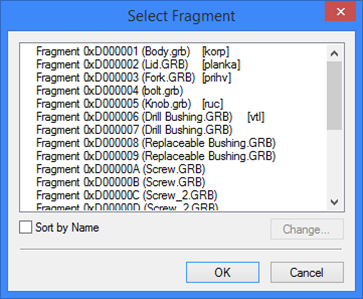
![]() <S> Select Fragment from List
<S> Select Fragment from List
This option can be helpful when the fragment with the known name is hard to find in the drawing. Besides, the option may be very helpful for editing the reference paths of several similar fragments simultaneously. A dialog box will appear in the screen, where you can select the desired fragment. By default, the fragments appear in the list in the order of their insertion into the assembly drawing. The flag "Sort by Name" alters the order of fragments in the list. The graphic buttons [Change] allows changing the filename, the reference paths or both, of the selected element (or a group of elements) in the list. |
|
The fragments which because of some reasons lost connection with the external file are marked with the question sign.
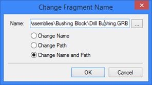
Selecting the option "Change Name" allows modifying the filename only, without changing the path.
Selecting the option "Change Path" modifies the path to the fragment without changing its name.
Selecting the option "Change Name and Path" modifies both the Name and the path of the fragment file.
We recommend using relative paths to the assembly or library rather than full paths, when inserting fragments. Using relative paths simplifies porting assembly drawings to different file systems.
In some cases, the system may automatically record the relative path to a reference with respect to the assembly file. Depending on the relative location of the fragment and the assembly file, the relative path to the reference may appear differently. The following table shows examples of relative path formats for fragment references:
Assembly location |
Fragment location |
Fragment reference path |
C:\Assembly.grb |
C:\Drawings\Parts\Part3.grb |
Drawings\Parts\Part3.grb |
C:\Drawings\Assembly_1\Assembly.grb |
C:\Part2.grb |
..\..\Part2.grb |
C:\Drawings\Assembly_1\Assembly.grb |
C:\Drawings\Assembly_1\Part1.grb |
Part1.grb |
Any |
Library "Bolts", file "Bolt_1.grb" |
<Bolts>Bolt_1.grb |
Follows are the rules that are accepted for the fragment reference relative path formats:
1. If the assembly is located at a higher level in the file tree, than the fragment, then the reference will be always relative to the assembly file. In this way, the portion of the full path to the reference, identical with that of the assembly file path, is removed, resulting in the relative path to the reference.
2. If the assembly is located deeper in the file tree, then the fragment, yet in the same tree branch of the file system, then T-FLEX CAD system will be able to create the relative path for the reference. In this way, to step up one level in the file tree, the system will use the notation "..\" in the beginning of the reference path. However, if the reference requires switching to another branch of the file tree, the user will have to specify the reference path manually, as the system won't be able to do this automatically.
3. If the assembly file and the fragment file are in the same folder, then the reference name will consist of just the fragment file name.
4. If the fragment file was inserted from an opened library, then the reference relative path will contain the library name, in brackets, and the fragment file name.
All fragments at once can be selected by the option:
![]() <*> Select All Elements
<*> Select All Elements
Upon selecting multiple fragments, the following options are available:
![]() <P> Set Fragment parameters
<P> Set Fragment parameters
![]() <Del> Delete selected Element(s)
<Del> Delete selected Element(s)
![]() <X> Automatic Explode
<X> Automatic Explode
![]() <Ctrl+X> Explode with Constructions
<Ctrl+X> Explode with Constructions
![]() <R> Select Fragment from List
<R> Select Fragment from List
![]() <I> Select Other Element
<I> Select Other Element
![]() <U> Update Fragment model
<U> Update Fragment model
![]() <Esc> Cancel selection
<Esc> Cancel selection
The options ![]() and
and ![]() explode the selected fragments, turning those into sets of drawing elements, with or without the original constructions.
explode the selected fragments, turning those into sets of drawing elements, with or without the original constructions.
The option call ![]() loads the changes from the fragment file.
loads the changes from the fragment file.
The available editing options for a single selected fragment are:
![]() <K> Input Fragment insertion points
<K> Input Fragment insertion points
![]() <P> Set Fragment parameters
<P> Set Fragment parameters
![]() <Y> Create Name for selected Element
<Y> Create Name for selected Element
![]() <Del> Delete selected Element(s)
<Del> Delete selected Element(s)
![]() <Ctrl><O> Open Part
<Ctrl><O> Open Part
![]() <O> Open Fragment in Context of Assembly
<O> Open Fragment in Context of Assembly
![]() <H> Update Fragment File (automatically updates the fragment document parameters per the current assembly)
<H> Update Fragment File (automatically updates the fragment document parameters per the current assembly)
![]() <X> Automatic Explode
<X> Automatic Explode
![]() <Ctrl+X> Explode with Constructions
<Ctrl+X> Explode with Constructions
![]() <T> Open Fragment file for editing
<T> Open Fragment file for editing
![]() <U> Update Fragment model
<U> Update Fragment model
![]() <C> Select Clipping Hatch
<C> Select Clipping Hatch
![]() <V> Inner Fragment Variables
<V> Inner Fragment Variables
![]() <Z> Change Fixing Vector
<Z> Change Fixing Vector
![]() <R> Select Fragment from List
<R> Select Fragment from List
![]() <I> Select Other Element
<I> Select Other Element
![]() <Esc> Cancel selection
<Esc> Cancel selection
Upon selecting a fragment, it will be marked by an outlining rectangle. All fixing points or the fixing vector of the fragment will be highlighted.
The option ![]() allows defining the fragment name. The fragment name can be used, for example, for search, automatic creation of the named nodes of the fragment in the assembly, for accessing the values of the fragment variables in the assembly drawing by the function get:
allows defining the fragment name. The fragment name can be used, for example, for search, automatic creation of the named nodes of the fragment in the assembly, for accessing the values of the fragment variables in the assembly drawing by the function get:
get ("Fragment name","Variable name"),
where "Fragment name" – the specified name of the fragment, and "Variable name" - the variable name in the fragment drawing, whose value is being accessed in the assembly drawing.
The selected fragment document can be opened for editing in a separate window, using the option ![]() . In this case, the parameters of the opened drawing will be those defined at its creation. The option
. In this case, the parameters of the opened drawing will be those defined at its creation. The option ![]() starts fragment editing in the assembly context.
starts fragment editing in the assembly context.
Option ![]() allows switching between fixing vectors defined in the fragment being inserted.
allows switching between fixing vectors defined in the fragment being inserted.
Option ![]() allows editing external variables of embedded fragments without opening of source fragment. After activation, you need to choose one of embedded fragments.
allows editing external variables of embedded fragments without opening of source fragment. After activation, you need to choose one of embedded fragments.
A detail drawing of the fragment can be obtained by the option ![]() . In this case, a new window is opened, with a copy of the fragment drawing loaded in it with the parameters corresponding to the assembly. The thus created drawing can be edited and saved under a new name, if necessary.
. In this case, a new window is opened, with a copy of the fragment drawing loaded in it with the parameters corresponding to the assembly. The thus created drawing can be edited and saved under a new name, if necessary.
Ways to Edit Fragments
Modifying fragment attachment
If a fragment has several fixing points, to change all their positions (or those of the fixing vector), use the option ![]() . After that, just as when inserting the fragment, subsequently define the position of each fixing point.
. After that, just as when inserting the fragment, subsequently define the position of each fixing point.
Modifying a particular fixing point (or a placement point of the fixing vector) can be done right after selecting the fragment. The order of steps in this case is described below.
The case of fragment attachment by fixing points
To modify a placement point, move the pointer to it and click ![]() . The fragment will start changing dynamically together with the cursor until the new location of the point is specified by clicking
. The fragment will start changing dynamically together with the cursor until the new location of the point is specified by clicking ![]() or by one of the automenu options:
or by one of the automenu options:
![]() <W> Dynamic Preview
<W> Dynamic Preview
![]() <I> Select next Fragment insertion point
<I> Select next Fragment insertion point
![]() <Esc> Cancel selection
<Esc> Cancel selection
To speed up handling of large fragments, the fragment rubberbanding can be turned off by the option ![]() .
.
The case of fragment attachment by fixing vector
To modify placement of a fixing vector point, move the pointer over it and click ![]() . The respective end of the fixing vector will start rubberbanding with the pointer. Set its new position by clicking
. The respective end of the fixing vector will start rubberbanding with the pointer. Set its new position by clicking ![]() or by one of the automenu options:
or by one of the automenu options:
![]() <W> Dynamic Preview
<W> Dynamic Preview
![]() <M> Fixing using two points
<M> Fixing using two points
![]() <M> Fixing using one point and angle
<M> Fixing using one point and angle
![]() <C> Mode of snapping to Connectors
<C> Mode of snapping to Connectors
![]() <Z> Change Fixing Vector
<Z> Change Fixing Vector
![]() <N> Select Node
<N> Select Node
![]() <I> Select next Fragment insertion point
<I> Select next Fragment insertion point
![]() <Esc> Cancel selection
<Esc> Cancel selection
Clipping fragment by hatch
The option ![]() is provided for selecting a hatch, whose contour will be used for clipping the fragment image. Upon selecting a hatch, only the portion of the fragment will be displayed that is within the contour of the selected hatch. If the image of the clipping hatch is not needed on the drawing, the hatch should have the parameter “hidden” set on.
is provided for selecting a hatch, whose contour will be used for clipping the fragment image. Upon selecting a hatch, only the portion of the fragment will be displayed that is within the contour of the selected hatch. If the image of the clipping hatch is not needed on the drawing, the hatch should have the parameter “hidden” set on.
Clipping by the hatch can be used if you need to use a hatch pattern not included in the standard set, perform the following steps:
· create a new document with a set of graphic lines representing a "hatch" pattern;
· in the document in which it is required to draw a nonstandard contour, create an invisible hatch the contour of which corresponds to the required one;
· insert the document with the hatch pattern created at the step one, as a fragment;
· call the fragment editing command and select the hatch fragment. Then, with the option ![]() select the contour of the invisible clipping hatch.
select the contour of the invisible clipping hatch.
The option ![]() ceases hatch clipping (this option appears only when editing a fragment clipped with a hatch).
ceases hatch clipping (this option appears only when editing a fragment clipped with a hatch).
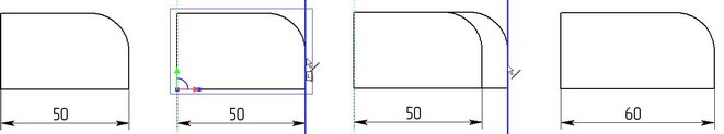
Editing external variables using draggers
For additional convenience, the system allows varying the fragment external variables dynamically by the mouse, using specially provided draggers. Draggers appear as thickened images of construction lines that are driven by external variables. This mode is on by default. Switching it On/Off is done within the document customizations on the tab "Preferences", the graphic button "Fragments".
Variables Editing for Several Fragments
The system allows the simultaneous modification of the variables with the same name for several fragments at once. For modifying the fragment variables it is necessary to perform the following actions:
●select fragments on the drawing;
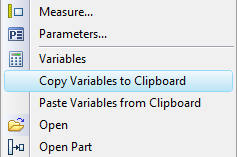
●invoke the context menu by pressing the right mouse button and choose the command “Variables”;
●introduce modifications in the dialog which appears.
Upon calling the command of the context menu “Variables”, the dialog with the list of variables of the selected fragments appears. This list may include either all variables of all fragments or only common variables (i.e., the variables with coinciding names). Control is carried out with a toggle “Show variables” at the bottom of the dialog.
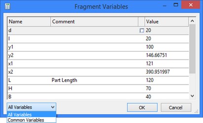
The common variables in different fragments can have different values. In this case, for such variables opposite their value there will be a special control element – a flag which when being switched on will let a user change the value. Modification of the value for the common variable will be applied to all selected fragments.
Using Clipboard for Fragment Variables
When selecting a specific fragment with |
|
Editing Fragment in Assembly Context
The option for editing in the assembly context ![]() is available in the context menu of the selected fragment and in the automenu of the command "EFR: Edit Fragment".
is available in the context menu of the selected fragment and in the automenu of the command "EFR: Edit Fragment".
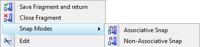
Upon calling the option, all elements of the assembly drawing other than those belonging to the fragment are drawn in halftone, and the fragment elements become editable. As in the assembly-context fragment creation, the user can create and/or edit the fragment drawing. With the associative or non-associative snapping to assembly elements turned on, you can use nodes and lines of the assembly drawing as references. The commands for modifying the snap types and exiting the mode of work in the assembly context can be found in the context menu.
![]()
Updating Fragments Files
The options "Refresh Fragment File" and "Refresh All Fragments Files" (the icon ![]() ) are provided for updating the fragment document per the changes in the assembly when working by “Top – down” approach or in the assembly context. To update a single fragment, you can use the respective option in the automenu of the command "EFR: Edit Fragment" or the command "Update", accessible in the context menu. To update all fragments per the changes in the assembly drawing, use the option "Refresh All Fragments Files" in the textual menu item "File|Fragment|Refresh Files".
) are provided for updating the fragment document per the changes in the assembly when working by “Top – down” approach or in the assembly context. To update a single fragment, you can use the respective option in the automenu of the command "EFR: Edit Fragment" or the command "Update", accessible in the context menu. To update all fragments per the changes in the assembly drawing, use the option "Refresh All Fragments Files" in the textual menu item "File|Fragment|Refresh Files".