Element Replacement


Element Replacement |
|
Let us reiterate that parametric properties of T-FLEX CAD models are managed by applying drawing elements over the construction entities. Meanwhile, all construction elements are defined using various geometrical relations with several base elements. This array of references from one element to another makes the model parametric. The command "RL: Replace Element" allows replacing a construction element by an element of the same type, that is, replacing all references to the original element in the model by references to another construction element. If necessary, the original element can be automatically deleted from the model upon the replacement.
The command "RL: Replace Element" can be called by one of the following means:
Icon |
Ribbon |
|---|---|
|
Edit→ Edit → Replace |
Keyboard |
Textual Menu |
<RL>, <Ctrl>+<H> |
Edit > Replace |
Upon calling the command, the following options become available in the automenu:
![]() <L> Select Line
<L> Select Line
![]() <C> Select Circle
<C> Select Circle
![]() <E> Select Ellipse
<E> Select Ellipse
![]() <S> Select Spline
<S> Select Spline
![]() <N> Select Node
<N> Select Node
![]() <I> Select Other Element
<I> Select Other Element
![]() <Del> Delete Source Element After Replacement
<Del> Delete Source Element After Replacement
![]() <Esc> Exit command
<Esc> Exit command
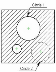
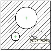
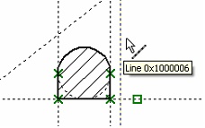
Let's review the use of the command on a simple example. A hatch is created in the drawing, whose contour was defined by a circle. We need to modify the model so that a different circle, "Circle 2", is used in the future instead of "Circle 1". That's use the command "RL: Replace Element" for this purpose. When using this command, the first step is selecting the source element. |
|
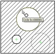
In the example, it is a circle. It can be selected using the option |
|
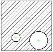
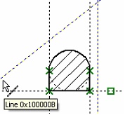
When selecting such element, only the elements of the same type as the source element will be pre-highlighted in the drawing. The only option available in the automenu will be the option for selecting elements of the respective type. In this example, select the "Circle 2". Upon selecting the source and the target construction element, confirm the element replacement using the option: |
|
In the course of the replacement, all the elements constructed relative to the source element are rearranged with respect to the target one. In this example, it was the hatch. If necessary, the source construction element can be deleted from the model upon the replacement. The mode of deleting the source element is turned on by the icon |
|
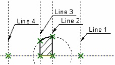
In the following example, the construction began with creating a vertical line – "Line 1". All later constructions were done relative to this line. The "Line 2" was constructed as parallel to the first one, and the "Line 3" - orthogonal, through the "Node 1". A tangency circle and the "Line 4" were later constructed relative to the two latter lines.
Let's replace the base line "Line 1" by a new line "Line 5".
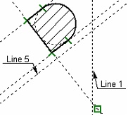
Upon the replacement, all construction elements that were defined relative to the "Line 1" are rebuilt relative to the "Line 5".
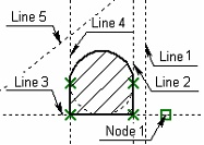
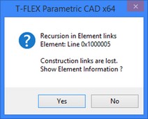
When using the command "RL: Replace Element", the target element should not be a child of the source one. Otherwise, a message is output about the encountered recursion.
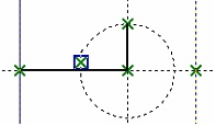
In the next example, the "Line 2" is constructed relative to the base line, "Line 1". In turn, the lines "Line 3" and "Line 4" are constructed relative to the "Line 2". A circle is created with the center at the intersection between the "Line 2" and the horizontal line in such a way, that it intersects the "Line 3" and not the "Line 4". An attempt to replace the "Line 1" by the "Line 2" in this model causes the message about recursion. |
|
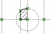
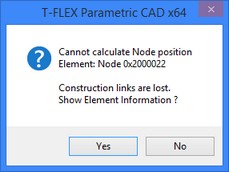
The command may also fail when some drawing element position cannot be defined relative to the target element.
For example, when creating the drawing of the above example, one of the nodes was defined as the node at the intersection between the circle and the "Line 3". An attempt to replace the "Line 3" by the "Line 4" will cause an error message, since the system will not be able to define the position of this node after the replacement.