Customizing List of Element Types for Selection


Customizing List of Element Types for Selection |
|
Customizing List of Element Types for Selection
The user can control the element types that are subject to selection by mouse ![]() . The selection filter icons are located in the right part of the system toolbar.
. The selection filter icons are located in the right part of the system toolbar.
![]()
To manage the filters, make sure the 3D window is active. To activate the window, click ![]() anywhere within.
anywhere within.
Element selection
3D element selection can be done either in the 2D or in 3D window. A 3D element selection in the 2D window is possible only if this 3D element creation was based on 2D elements. For example, consider a 3D node defined by two 2D nodes. It can be selected either directly in the 3D window or via any of the two 2D nodes in the 2D window. Either way results in the 3D node selection.
The elements of a 3D sketch can be selected while in "3D Drawing" mode just the same way as in the 2D window.
Selecting a 3D element
Pre-highlighting is turned on in the 3D window. When the cursor approaches an element on the 3D scene, the element is getting highlighted, and the cursor gets an attached glyph that indicates the type of the highlighted element. If the cursor is briefly held over the element, a pop-up help appears displaying the type of the element. To select the element, press ![]() . To select a group of elements, hold the <Shift> key while selecting.
. To select a group of elements, hold the <Shift> key while selecting.
In complicated models, several elements of the same or different types can be under the cursor simultaneously. In this case, use the "Other…" button of the context menu that provides selection from list. The list is composed of the elements nearest to the cursor, whose types are admitted by the selection filter. An alternative way is to point the cursor at the desired element and briefly hold still. The cursor will be appended a "scroll list" glyph, and a pop-up widget will appear indicating the total number of elements available for selection at this point, and a current element type. The widget allows scrolling through the elements with the mouse middle wheel button (if equipped). Pressing ![]() selects the currently highlighted object.
selects the currently highlighted object.
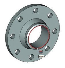
To select a 3D profile, point the cursor at the contour line. To select bodies, set up the selector for operation selection and turn off edge and face selection. If in "Shading" or "Render" display mode, point anywhere on the body. In "Wireframe" mode, point at an edge of the body. Since the bodies may overlap on the scene, re-orient the model to bring the desired body up front.
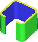
The selected elements are marked with a color, depending on the object type and the purpose of selection. All color settings are defined in the system customization functionality. In some 3D commands, different elements of the same type are marked with different colors. For example, in the three-face blending operation, the user specifies the left, right and middle sets of faces. In this case, the faces of each set are marked with different colors. These colors also mark the respective tabs of the property window dialog box, that contain the corresponding lists of faces.
When working with large 3D assemblies containing nested fragments, only the fragments of the first embedment level are selected in 3D window. To get a quick access to the nested fragments of a lower level, it is possible to use the ![]() option found on the system toolbar.
option found on the system toolbar.
Selecting elements within a command
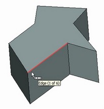
The user often needs to select some existing elements on the 3D scene when defining a command input data. The system automatically adjusts the selector for the element type required by the current step in the command automenu. Suppose, for instance, while defining a blend we pushed the option "Select edge". The selector then adjusts to edge selection only. Next, reorient the scene for easy selection, point the cursor at the desired element, and press ![]() . In this case, selecting a group of elements is done by picking subsequently, without holding the <Shift> key.
. In this case, selecting a group of elements is done by picking subsequently, without holding the <Shift> key.
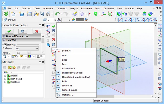
Often, a required geometrical input in a command may be defined by a number of different-type 3D objects. Thus, for instance, a direction can be defined by wire objects, such as edges, paths, profiles, etc., or by a pair of 3D nodes, or by a normal to a planar surface, etc. In this case, the automenu option provides an extended list of filter settings for the selector. The availability of the list is indicated by a black triangle in the right-bottom corner of the option button. A simplified representation of the list is also displayed in the system bar.
Should a wrong element get selected (say, a neighboring one), use the automenu option,
![]() <I> Select Other Element
<I> Select Other Element
A subsequent pick on the icon switches the selection to the next nearest element, on and on until all elements are traversed. This option is available with all 3D commands that require object selection.
Canceling selection
While within a command, element selection can be cancelled by pressing ![]() or <Esc> key. The elements are getting unselected one by one in the reversed order of the selection. Many commands allow unselecting all elements at once by using an appropriate automenu icon. (Refer to the respective topics in the documentation.)
or <Esc> key. The elements are getting unselected one by one in the reversed order of the selection. Many commands allow unselecting all elements at once by using an appropriate automenu icon. (Refer to the respective topics in the documentation.)
To cancel selection of an element or a group of elements while outside any command, simply select another element or click ![]() at a blank on the 3D scene.
at a blank on the 3D scene.
Element search
Search functionality can be invoked in transparent mode, and is available with all commands. For quick access to the search command, the button ![]() found in the set “Edit” of the main toolbar can be used.
found in the set “Edit” of the main toolbar can be used.
Advanced search can be performed by the command "Edit|Find… ".