Lofted Bend


Lofted Bend |
|
SML: Lofted Bend operation is used to build bending by sections:
Icon |
Ribbon |
|---|---|
|
Sheet Metal → Lofted Bend |
Keyboard |
Textual Menu |
<SML> |
Operation > Sheet Metal > Lofted Bend |
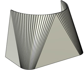
Lofted Bend operation is intended for modeling complex sheet bodies basing on two sections.
To build a sheet body you need to select two sections lying in two planes that can be either parallel or not. The sections can consist of smoothly joined arcs or straight lines.
The number of arcs and straight lines in two sections is not necessarily the same. When building the bend arcs will connect to arcs and straight lines – with straight lines, and cylindrical bend segments will be formed.
The body obtained as a result of this operation can be unbent with the help of SMU: Unbend operation.
Command parameters
General parameters section.
Faceted approximation. The option enables users to build a surface consisting of planes set by three or four points. The surface obtained can be subsequently transformed into sheet metal, setting appropriate bending radii and weakening for the edges.
Unfolding approximation. The option enables users to build a body by the surface which can be unfolded.
Thickness. This parameter is general for all the sheet metal commands. The parameter value sets thickness of the sheet body being built. By default it is set in SMP: Defaults command.
The variant of push-out direction at the given thickness relative to the plane built by the two selected sections has three variants similarly to Create Part operation.
|
Outside |
|
Inside |
|
Symmetric |
Radius. This parameter is general for all the sheet metal commands. The parameter value sets radius for all the bends of the body being built.
Additional settings section:
Accuracy. The less is the value, the higher is the accuracy of building the body. High accuracy increases number of bends and requires more time for building the body.
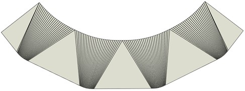
Bends. The option enables users to manually set total number of bends taking into account the nearest possible number.
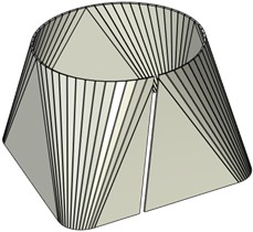
|
|
30 bends |
60 bends |
Gap. This option enables users to set the gap at the sheet part in case of using closed contours.
Simplify. Eliminates (processes) the faces whose size does not allow to correctly build a 3D model from calculation.
Command automenu options are:
|
<Ctrl+Enter> |
Finish input |
|
<P> |
Set entity Parameters |
|
<X> |
Exit command |
|
<F5> |
Preview Operation Result |
|
<U> |
Select first section |
|
<V> |
Select second section |
|
<1> |
Select starting point for the 1st section |
|
<2> |
Select directions for the 1st section |
|
<3> |
Select starting point for the 2nd section |
|
<4> |
Select directions for the 2nd section |
Finish input. To build geometry according to the given parameters. In case the parameters are insufficient, the option in not available.
Set entity Parameters. Call a standard 3-D design command parameters dialog.
Exit command. Shuts down the command cancelling the given parameters.
Preview Operation Result. The option enables/disables a standard option for reviewing 3-D design commands.
Select starting point for the 1st section. In case of an unclosed section the point will be selected automatically. With the help of this option you can set the point manually, e.g. when only a part of the unclosed contour is used. In case of a closed contour the point is to be set obligatory. The point will be selected at the contour under the cursor at pressing ![]() , according to possible bindings. You can also pre-create a 3D node. The point will determine the plane position by which the cutting will be performed. If only the first section point is given, the plane will be perpendicular to the contour.
, according to possible bindings. You can also pre-create a 3D node. The point will determine the plane position by which the cutting will be performed. If only the first section point is given, the plane will be perpendicular to the contour.
Select directions for the 1st section. In case of an unclosed contour the option is not obligatory. In case of a closed contour it is necessary to set the plane or face determining the directing vector. The vector projection onto the tangent to the contour in the initial point will determine the points counting direction.
Select starting point for the 2nd section. The option is similar to the first section initial point. The option is not obligatory: the initial point of the second closed section will be selected automatically as the intersection point of the section outline with the normal plane set by the first section initial point. Initial points of the first and the second sections (in case they are closed) determine the cutting plane where the gap is set.
Select directions for the 2nd section. The option is not obligatory. The counting direction at the second section is automatically set the same as at the first one. The operation principle is similar to choosing the direction for the first section. The directions at the first and the second contours must be the same.
Creating a bend by sections
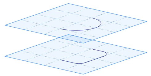
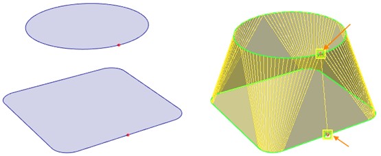
Unclosed sections
A sheet body can be built of two unclosed sections.
To select the sections automenu options of selecting the sections ![]() and
and ![]() are used.
are used.
If necessary a sheet body can be built by a part of the contour only. You need to select a point ![]() and counting direction
and counting direction ![]() for the first and the second contours. The contour counting directions must be the same.
for the first and the second contours. The contour counting directions must be the same.
In the example in the picture a plane is chosen to determine the counting direction.
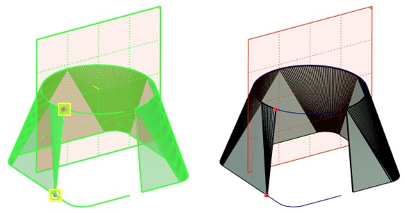
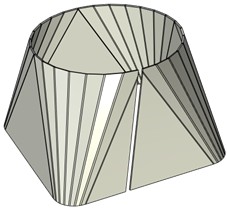
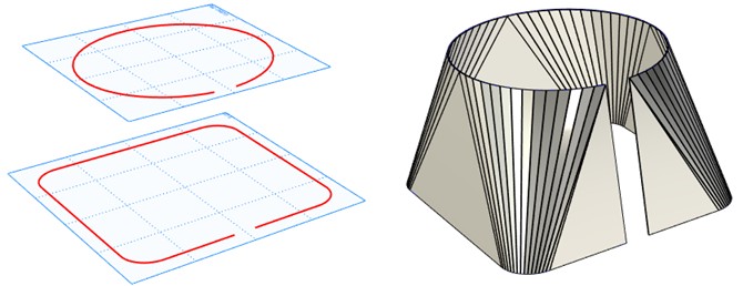
Closed sections
A sheet body can be built by two closed sections.
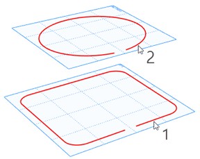
You need to additionally set the initial point and counting direction at least for the first section.
The cutting plane can be set by selecting the initial point at the first section. Selecting the initial point at the second section enables users to set the cutting plane incline manually.
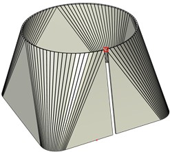
|
|
A 3D node at the upper section and counting direction are chosen |
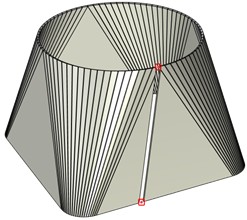
Two 3D nodes at the sections and counting direction are chosen |