Offset Curves


Offset Curves |
|
Offset curves are created by offsetting an arbitrary geometrical object by a specified amount. Offset curves are created based on existing curves (splines, ellipses, functions). The shape of an offset curve depends on the shape of the original curve and the amount of offset. The latter can be defined by a variable.
For such system entities as a circle and a line, offsets can be created on the fly together with the original entity creation.
A most typical application of offsets is pipe modeling. It is quite convenient for the user to draw just the centerline, and then create the offset lines of the pipe silhouette. Offsets are also widely used in developing structural and architectural drawings.
Creating offset curves
Offset curves are created in the command "TO: Construct Offset Curve". The command is called as follows:
Icon |
Ribbon |
|---|---|
|
Draw → Construct → Offset Curve |
Keyboard |
Textual Menu |
<TO> |
Construct > Offset Curve |
Upon entering the command, the following actions become available:
![]() <Enter> Select element
<Enter> Select element
![]() <P> Set Construction Line parameters
<P> Set Construction Line parameters
![]() <S> Select Spline
<S> Select Spline
![]() <E> Select Ellipse
<E> Select Ellipse
![]() <F4> Execute Edit Construction command
<F4> Execute Edit Construction command
![]() <Esc> Exit command
<Esc> Exit command
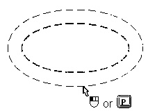
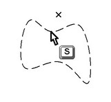
Offset curve creation begins with the selection of the reference element to use for offsetting. The reference element is selected by the cursor. For an accurate selection, use the options <S> "Select Spline" or <E> "Select Ellipse", while pointing the cursor to the respective element. The selected element will highlight, and the offset curve will start rubberbanding. Move the cursor over the desired position and click |
|
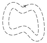
The offset distance can be entered in the "Offset" input box of the element parameters dialog. Positive offset values correspond to outer positions of the offset curve with respect to the reference element, while the negative - to inner positions, respectively. In the case of using the mouse input |
|
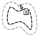
Offset position can also be defined using an existing node. To do this, select the reference element for the offset curve. This brings the following option in the automenu:
![]() <N> Select Node
<N> Select Node
Use this option for selecting a node the offset curve will be passing through.
To reject a reference element selection, use the option
![]() <Esc> Cancel selection
<Esc> Cancel selection
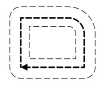
Offsets can be constructed to composite objects made of various-type entities, such as a spline and a line. To do this, first create a 2D path along the desired contour, and then use the path for offsetting. The corners of the reference curve become rounded on the offset curve, as rounding is adopted for handling offset corners in T-FLEX CAD. |
|
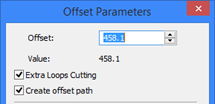
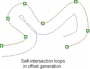
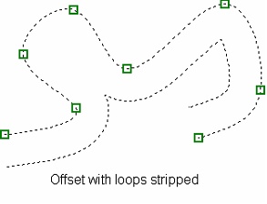
When a spline offset is generated, self-intersection loops may occur in the offset contour. The offset parameters dialog box provides the option for loops stripping.
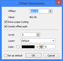
Offset parameters
Offset parameters can be defined at creation or editing time. The parameters dialog box is called by the option Offset. Defines the distance between the reference element and its offset curve. The input can be a number, variable or expression. Extra Loops Cutting. This parameter turns on the loop stripping mode. In this mode, all self-intersection loops are stripped off the offset contour. Precise Circle and Arcs Calculation. This parameter is material only for creating an equidistant line with respect to a given 2D path. When activating this flag, instead of an equidistant construction line, the 2D path with more accurate processing of arcs and circles will be constructed. Level. Places the offset curve on a certain visibility level. Layer. The name of the layer the offset belongs to. Set as default. Setting this flag means the current dialog box settings will be used as defaults for newly created construction entities. |
|
Editing offsets
Editing offsets, as well as other construction entities, is done in the command "EC: Edit Construction".
Icon |
Ribbon |
|---|---|
|
Draw → Additional → 2D Construction |
Keyboard |
Textual Menu |
<EC> |
Edit > 2D Construction |
An offset can be selected by pointing the cursor and clicking it ![]() , or using the option
, or using the option
![]() <S> Select Spline
<S> Select Spline
The selected offset curve gets highlighted.
The following options become available in the automenu:
![]() <P> Set Construction Line parameters
<P> Set Construction Line parameters
![]() <V> Mode of dynamic recalculation of model
<V> Mode of dynamic recalculation of model
![]() <Y> Create Name for selected Element
<Y> Create Name for selected Element
![]() <K> Break link with variable
<K> Break link with variable
![]() <I> Select Other Element
<I> Select Other Element
![]() <Del> Delete selected Element(s)
<Del> Delete selected Element(s)
![]() <Esc> Cancel selection
<Esc> Cancel selection
Editing of an offset is none different from its creation.
The offset editing command "EC: Edit Construction" can also be accessed from the command "TO: Construct Offset Curve" using the option:
![]() <F4> Execute Edit Construction command
<F4> Execute Edit Construction command
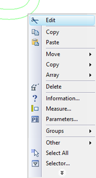
The third way of selecting an offset curve for editing is available while no command is active (in the command waiting mode). Move the cursor over the offset and right-click ![]() for the context menu. Selecting the menu item "Edit" launches the offset editing command. The item "Delete" allows deleting the selected element. Selecting the "Parameters" command opens the offset parameters dialog box. .
for the context menu. Selecting the menu item "Edit" launches the offset editing command. The item "Delete" allows deleting the selected element. Selecting the "Parameters" command opens the offset parameters dialog box. .