By Parameters


By Parameters |
|
Main concepts
A parametric sweep is a variation of a common sweep. This operation is used for creating bodies with complex surface geometry. The resulting body is obtained by "sweeping" a profile along an arbitrary or specially defined spatial trajectory. In this case, the system allows defining the variation of the profile parameters as a function of its position.
"Sweeping" of the profile is realized by multiplicating the original profile. The thus created set of profiles shapes up the resulting body. The body can be closed. Depending on the profile geometry type (sheet or wire), the resulting body may be a solid or a sheet.
The driving parameter of the operation is the profile instance number ("copy number"). Numbering of profile instances ("copies") starts from 1 and is automatically incremented by 1 per an instance as the operation creation progresses.
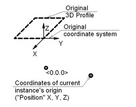
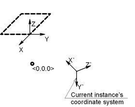
The so-called current instance coordinate system is computed for each instance of the profile. Each instance of the original profile is carried over from the original coordinate system to the computed coordinate system of the current instance. The user can select one of the model's local coordinate systems as the original coordinate system. If no local coordinate system is selected, then the global coordinate system is used as the original coordinate system.
The origin and orientation of the coordinate axes of the current instance can be done in two ways. One can specify the rules of varying the coordinate system parameters by an expression. The other way implies the use of a 3D Path or another body surface for positioning the coordinate system of the current instance in space. Each way will be described in details below. The user controls the position and orientation of each profile instance by manipulating the respective coordinate system.
The operation parameters dialog box provides controls over the coordinate system parameters of an instance. The two main types of the operation parameters are - driven parameters and driving parameters.
Driven parameters – are those whose values are computed automatically as the operation creation progresses. Independent variables can be used for reading the values of such parameters.
Independent are those system variables that are assigned a specific value, rather than an expression. Those do not depend on other system variables. On the contrary, some of the parameters of 2D or 3D constructions may depend on such variables, as well as other driven, or dependent, variables.
A name of an independent variable used with driven parameters is always selected from the list of already existing independent variables in the system.
The parameter "Number of Copy" is always driven. Always use an independent variable to read this parameter for getting the current copy number as the operation creation progresses.
How to use driven parameters?
You can enter the name of an independent model variable in a driven parameter value box to establish a relation between the parameters of positioning an instance in the space and the parameters defining the shape of that profile instance. After computing the position of the coordinate system of the current profile instance, the independent variables assigned to the driven parameters are updated with the respective current values. If an assigned independent variable is somehow involved in defining the profile geometry, then, at each instance creation, the values of the driven parameters will be passed through that variable on to the related model parameters. Thus, the shape of the profile will be recalculated depending on the values of the driven parameters.
The variable that reads the current copy number can be bound to record numbers in a database.
Driving parameters are the fields whose values are defined by the user. An arbitrary expression can be entered in the input box of a driving parameter. Such an expression can include any system variable. For example, you can include the variable that represents the copy number. In this case, you will get a dependency of the parameter on the copy number via that specified expression.
The computations on the way of the operation creation are performed in the following order: the instance counter ("copy number") is incremented; the driving parameters are computed; the driven parameters (if any) are computed; the original profile is recalculated with the current values of the variables; the thus obtained instance is positioned.
Steps of operation creation
Follows are the means of calling the command:
Icon |
Ribbon |
|---|---|
|
3D Model → Create → By Parameters |
Keyboard |
Textual Menu |
<3SA> |
Operation > By Parameters |
The following icons become available in the automenu:
|
<R> |
Select Contour |
|
<F> |
Cancel contour selection |
|
<1> |
Select Curve defining position of coordinate system |
|
<2> |
Select Curve defining X direction of coordinate system |
|
<3> |
Select Curve defining Y direction of coordinate system |
|
<4> |
Select Surface defining X direction of coordinate system |
|
<5> |
Select Surface defining Y direction of coordinate system |
|
<6> |
Select source LCS |
|
<7> |
Cancel selection of elements defining coordinate system |
Depending on the way of defining the coordinate system of the current instance, some parameters may appear as driving or driven. In this case, there are two main approaches to creating a body with parametrically varying profile:
●The approach of free instance orientation
●The approach of orienting instances by paths or surfaces
In each case, different automenu options are used, and a different sequence of steps is involved for defining the necessary elements and operation properties. Follows are the descriptions of each approach presented separately.
Free instance orientation approach
To create a parametric sweep, simply select a 3D profile, specify the number of instances and assign an independent variable to the parameter "Number of Copy". Using the variable that follows the instances enumeration, one can create certain dependencies for the driving parameters, as well as for 2D or 3D constructions, which, in turn, define the shape and position of the 3D profile.
One can select the 3D Profile by using the respective option in the automenu:
![]() <R> Select Contour
<R> Select Contour
The number of profile instances can be specified in the operation parameters dialog box on the tab "Operation".
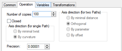
Besides the "Number of Copies" parameter, this tab also contains an accessible option "Closing". With this option on, the body being created from the set of the sections (the set of the instances of the original profile), will be smoothly closed, as if the first section was selected twice.
After defining the number of instances, one can proceed to the tab "Variables". This tab has two types of parameters, grouped under the names "driving parameters" and "driven parameters".
When creating the operation following this approach, the only driven parameter is the copy number, while the driving are the parameters responsible for positioning the current profile instance in space. For convenience, four groups of driving parameters are defined: Position, X axis direction, Y axis direction, Z axis direction.
The "Position" group controls the X, Y, Z coordinates of the point defining the origin of the current instance coordinate system.
The rest of parameters define the three vectors used for orienting the coordinate system of the current instance.
You can explicitly describe the position of the current instance coordinate system as a function of the copy number. To do this, define the required dependency in the group of driving parameters (by entering the names of existing variables that directly or indirectly depend on the copy number).
Each vector defining the direction of a coordinate system axis of an instance is defined by two points. The first point coordinates are <0,0,0>. The coordinates of second points of the direction vectors for the current instance's coordinate system axes are defined by the parameters X, Y, Z from the respective group of driving parameters.
In the case when the vectors defined by the user are not orthogonal or do not make a right-oriented coordinate system, the system refines the definition automatically. Axes definition is done in the order: X, Y, Z. The X-axis direction is left unchanged, the Y-axis is rotated to yield the 90° angle in the XY plane, and then the Z-axis is defined.
In the case when only two vectors are defined (for example, the X and Z-axes), then the order of defining vectors changes, and the third vector (of the Y-axis) is defined last.
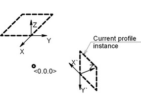
Each profile instance is obtained by carrying a copy of the original profile from the global coordinate system to the computed at the given step coordinate system of the current instance.
Additionally, one can select a local coordinate system by using the automenu option:
![]() <6> Select source LCS
<6> Select source LCS
In this case, the selected coordinate system will be used instead of the global one when carrying over the copies of the original profile.
When creating a parametric sweep following the described approach, the system computes the position and orientation of the current instance of the profile in the following order:
1. The variable reading the copy number is incremented.
2. The absolute coordinates are computed of the origin of the current instance coordinate system. The computation is based on the expressions entered in the driving parameters fields (the group "Position").
3. The coordinates of the vectors are computed, defining the directions of the current instance's coordinate system axes. The computation is based on the expressions entered in the driving parameters fields (the group "Direction")
4. The coordinate system of the current instance is created in the computed point of the origin, oriented according to the computed direction vectors.
5. If the geometry of the 3D profile depends in some way on the variable that reads the current copy number, then the profile will be recalculated with the current variable value.
6. The original profile's copy is carried over from the original coordinate system to the obtained coordinate system of the current instance. If the original coordinate system was not specifically selected, then the global coordinate system is used as the original when carrying over a copy of the profile. After computing all instances of the original profile, the result is united in one solid or sheet body using spline surfaces. |
|
Example 1
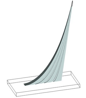
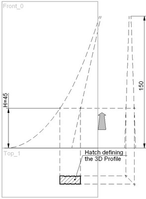
As a first example, let's create a rather simple model (see the diagram on the right hand side). Let's skip the details of creating the auxiliary 2D and 3D construction elements. Instead, let's briefly review the technique itself. The file corresponding to this example is located in the library “Examples”, in the folder "…\3D Modeling\By parameters\ By parameters 3.GRB" This model can be created by sweeping a 3D profile in the space that is indirectly tied to several guides. Let's use four guides in the 2D view, two of which will define the elevation view, and the other two - the left side view. Three guides are straight lines, and one is a spline.
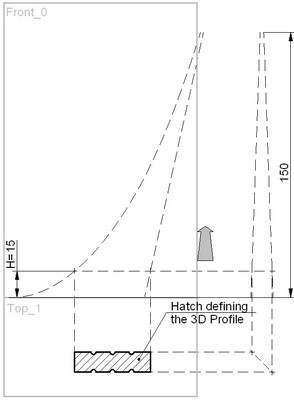
The horizontal construction line is drawn. The position of this line is defined by the expression
"H-1". Therefore, it depends on the variable "H".
Since the "Number of Copy" parameter values sequence begins from one, sometimes a correction (–1) is required in the expressions where the variable "Number of Copy" is entered. In this example, the first instance of the profile should be located at the base, that this at the coordinate Y=0.
Four 2D nodes are constructed at the intersections of the horizontal line and the guides. These nodes can drive the length and width of the profile if attached to vertical lines. A 3D node is created based on one of the 2D nodes in order to fix the profile plane. The grooves on the sides of the profile are constructed in such a way to always divide its side in four equal parts. The grooves radius linearly depends on the length of the profile.
We will need two workplanes – the elevation view and the plan view. The first one is needed for constructing the 3D node, the second - for the profile. The coordinate system origin is located at the model base level (see the diagrams). A straight line is constructed from the origin at the angle of 45° to the horizontal. This line is necessary for establishing the projective relation between the guides on the left side view and the profile hatch on the plan view.
All constructions are interlocked so that varying the variable "H" causes the following chain of modifications: the horizontal line changes its position, that affects the position of the 2D nodes referencing the line. The next link in the chain is modification of the profile hatch geometry and repositioning of the 3D node, to which the 3D profile plane is snapped. Consequently, the 3D profile itself will move in the space.
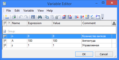
Among the operation parameters, the variable "H" should be assigned the copy number. Specify the number of copies in the "Operation" tab, corresponding to the type of the model, amended as (150+1=151).
It is not necessary to describe the rule for adjusting the instance's coordinate system, since the original profile adjusts its position due to a direct dependency on the copy number. As a result, each instance's coordinate system coincides with the global coordinate system, and, therefore, the current copy coincides with the original profile in the position and geometrical parameters. What matters is how the original profile moves with variations of the variable "H", that is, with respect to the copy number.
The described approach is convenient for using two-dimensional drawing data for constructing a complex model.
Example 2
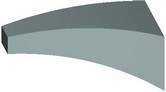
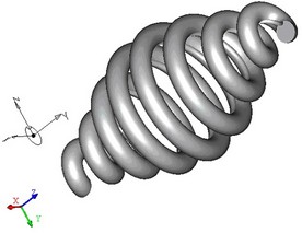
The second example demonstrates the approach to the model creation, when the exact rule is defined for the profile movement. This example is located in the library “Examples”, the folder “\3D Modeling\By parameters\ By parameters 1.GRB”. The original data for creating this operation are: a 3D profile; a local coordinate system constructed in the center point of the profile and oriented with respect to the profile as shown in the diagram (the Z-axis lies in the profile plane and is directed towards the groove); several independent variables.
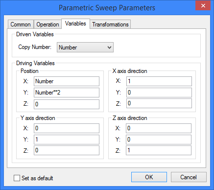
The expressions should be entered in the operation parameters fields, as shown in the following diagrams:
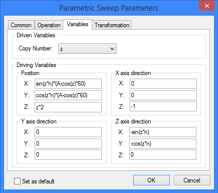
The expressions in the "Position" group define the helical trajectory with changing radius. The radius is varied by the cosine function.
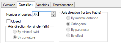
The number of copies (profile instances) is equal to 360 due to the following reason: the 360-degree period is used in the expressions of trigonometrical functions.
The diagram shows that the Z-axis of the original profile coordinate system should always be directed towards the center of the spiral (with the groove towards the center), the X-axis – in the opposite direction to the Z-axis of the global coordinate system. The expressions describing these rules are entered in the respective fields of the driving parameters. The Y-axis is defined automatically.
The approach of orienting instances by paths or surfaces
Since it is not always possible to describe the rules of the profile instance's parameter modifications by expressions exactly, it is sometimes convenient to use 3D paths or surfaces from other bodies for defining the position and orientation of the current instance's coordinate system.
The origin of the current profile instance's coordinate system is snapped to a 3D path. The position of the origin on the paths can be controlled in two ways.
The X- and Y-axes can be oriented using other 3D paths or surfaces from other bodies.
Selection of a 3D path for snapping the coordinate system origin of the instances is done by the option:
|
<1> |
Select Curve defining position of coordinate system |
Selection of elements for defining the orientation of the X and Y-axes is done by the following automenu options (the Z-axis is defined automatically):
|
<1> |
Select Curve defining position of coordinate system |
|
<2> |
Select Curve defining X direction of coordinate system |
|
<3> |
Select Curve defining Y direction of coordinate system |
|
<4> |
Select Surface defining X direction of coordinate system |
|
<5> |
Select Surface defining Y direction of coordinate system |
When creating the operation using 3D paths, the operation dialog tabs "Operation" and "Variables" are somewhat different from the described above:
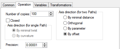
Accessible in this tab are various options for controlling the axes directions. Which group is accessible depends on how many paths were selected altogether: one (for defining the instance's coordinate system origin only) or two (for defining the instance's coordinate system origin and orientation of the X and/or Y-axes).
The group "Axis direction (for single Path)":
By curvature. The X-axis coincides with the direction of the path's curvature vector. If the 3D path is a straight line, then the axis is oriented along the X-axis of the global coordinate system.
By minimal twist. The X-axis is directed so to provide smooth rotation from the curvature vector direction at the path start to the curvature vector direction at the path end.
The Z-axis is always directed along the tangent to the path at the point of the coordinate system origin of the current instance.
The Y-axis direction, if not defined, is determined automatically based on the X- and Z-axes.
The group "Axis direction (for two Paths)":
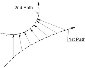
By minimal distance (between the paths at the origin). A vector is constructed from the instance's coordinate system origin on the first path towards the nearest point on the second path. |
|
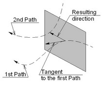
Orthogonal (to the path). A plane is constructed orthogonal to the first path tangent direction in the coordinate system origin. The axis direction is defined by the intersection point between the plane and the second path. If such point can't be constructed, an error message is output. |
|
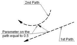
By parameter/By offset. An expression entered in one of these boxes is evaluated to define the point on the second path that determines the axis direction.
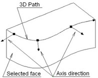
If a face is selected for defining the axis direction, then, in the general case, a point is identified on the face that this nearest to the coordinate system origin located on the path. The normal to the face's surface in this point determines the axis direction. The result will be best when the coordinate system origin lies in the surface. Therefore, use of a face for orienting the axes of the profile instance is recommended in the cases, when the first 3D Path lies on that face. |
|
The thus constructed X- and Y-axes may not be orthogonal (if those are parallel, the system will output an error message). In this case, the Y-axis will be additionally reoriented to become orthogonal to the X-axis in the plane defined by the two axes. The Z-axis will be determined automatically.
If a path or face is specified for the X-axis and not for the Y-axis, then the Z-axis will be directed tangent to the path defining the position of the coordinates origin, while the Y-axis will be determined automatically. If the X and Z-axes are not orthogonal, then the X-axis is additionally reoriented in the way described above.
Let's examine the "Variables" tab:
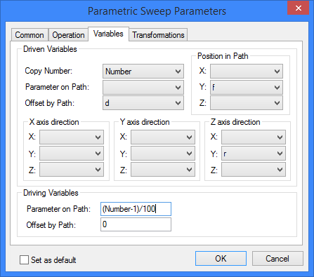
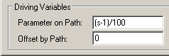
As shown in the diagram, the group of driven parameters now includes not only the parameter Number of Copy, but also the groups Position in Path, X axis direction, Y axis direction and Z axis direction. There are now additional parameters Parameter on Path and Offset by Path.
The group of driven parameters "Position in Path" allows reading the absolute coordinates of the current instance's coordinate system origin. The driven parameters from the groups "X/Y/Z axis direction" provide the coordinates of the instance's coordinate system axes. You can use the information about the position and orientation of the current profile instance in the space for defining relations with other model parameters.
The group of driving parameters includes Parameter on Path and Offset by Path. Parameter on Path and Offset by Path serve the same purpose – to define the point position on a path by various means. Therefore, you can't simultaneously define both the Parameter on Path, and Offset by Path. Parameter on Path varies in the range from 0 (at the start of the path) to 1 (at the end of the path); Offset by Path is measured in the model units and is equal to the length of the portion of the path from the start to the desired point.
Once you defined the Parameter on Path driving parameter, you can assign the driven parameter to the Offset by Path only, and vice versa.
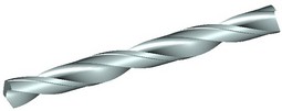
Example 3
Let's review a parametric sweep creation using 3D paths on an example of the model of a drill bit's cutting tip. The file with this example is located in the library “Examples”, the folder “\3D Modeling\By parameters\ By minimal distance.GRB”. |
|
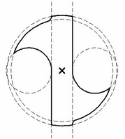
Create a new document using the template with workplanes. The next step is creation of the 3D profile. For this purpose, activate the workplane "Top view" and draw a contour as shown in the diagram. For convenience, try to construct the profile in such a way, that its center is located at the global coordinate system origin. In this case, you do not have to construct the local coordinate system for tying instances of the profile to the 3D path during the operation creation. |
|
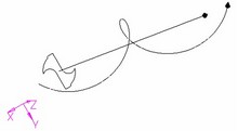
Next, we need to create two 3D paths for positioning the profile in the space when creating the parametric sweep. The path defining the profile position is a straight line coinciding with the axis of the bit. It can be created by two 3D nodes constructed on the axis of the bit. The length of this path defines the length of the cutting portion of the bit. The other path defines the profile orientation in space and is represented by a spiral line. The second path can be easily constructed using a cylindrical worksurface. |
|
In the valuable editor, create an independent variable for storing the value of the copy number. In this example, the created variable was named s.
After calling the operation creation command, select the 3D profile, the 3D path defining the profile position and the 3D path defining the direction of the X-axis. On the "Operation" tab of the operation parameters dialog, define the number of copies equal to 101 (with the correction) and select the option By minimal distance for the two paths.
On the "Variables" tab, select the variable s to assign the copy number. This is the only necessary driven parameter in this example.
Enter the expression in the driving parameter "Parameter on Path" input box, that will define the profile position along the path depending on the copy number. Remember that the Parameter on Path varies in the range from 0 to 1.