Element Relations


Element Relations |
|
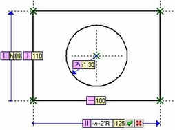
To quickly track geometrical dependencies in drawings and manage them, T-FLEX CAD has a special type of 2D elements – Relations. Relations serve to visually render on the drawing screen the types and parameters of geometrical dependencies between construction elements. Using the relations one can modify parameters of those dependencies without calling the editing commands of the respective construction elements.
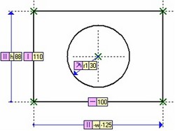
Relations are auxiliary objects that are displayed in the drawing field in the way of special marks. Those are not printed and are not exported. The information about the type of the geometrical dependency and the numerical parameter of the object, to which a relation pertains, is displayed on the relation mark. If a parameter is related with an expression or with a variable, then the relation mark displays both the expression and its current value.
Relations can be created automatically by the system ("temporary Relations") or manually by the user.
The automatic creation is done in the command for editing construction lines and graphic lines created based on construction lines. The system creates relations and displays them on the screen: if a construction line is edited – then for that line itself, if a graphic line is edited – then for the construction line, on whose base the graphic line is created. When exiting the editing command, such Relations are deleted automatically. Temporary Relations can be used to modify construction line parameters in the transparent mode.
Manual creation of Relations is done by the user in the command "REL: Element Relations". In this case, it is possible to create Relations either for individual construction elements or for all construction elements in a given drawing. Relations that are explicitly created by the user exist in the drawing up until the user deletes them by the same command. By default, those are permanently displayed in the drawing. Using those you can analyze parametric relations in the model, as well as modify construction line parameters. If necessary, all or specific existing Relations can be hidden from the current 2D window or completely over the entire document (such hidden Relations will not be displayed in any 2D windows opened for this document).
Using Relations when Working with Drawings
Relations serve the two main purposes:
- Visualizing geometrical relations in the model;
- Modifying geometrical parameters of the model in the transparent mode.
The first goal is achieved by creating Relations, when the user can visually examine geometrical relations without using the command "Help|Information…". To modify an existing geometrical parameter using Relations, point the mouse at the parameter value in the Relation mark and click ![]() . The mark will turn to an edit box displaying the parameter value it controls.
. The mark will turn to an edit box displaying the parameter value it controls.
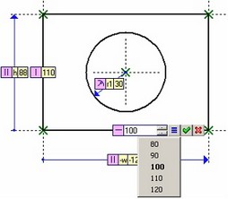
Just like in other system fields for editing values, the user can create here the list of frequently used parameter values and use it with the help of a special button for selecting the value from the list. This list is created with the commands of the context menu called by ![]() in the editing mode of selected Relation. “Font” command can modify font that will be used for displaying the Relation marks.
in the editing mode of selected Relation. “Font” command can modify font that will be used for displaying the Relation marks.
Font parameters are common for all “marks”: Relation marks, dimension marks used for editing dimension values in transparent mode, dragger marks in 3D operations.
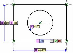
The new parameter value can be fixed by clicking the ![]() button on the mark itself or in the automenu.
button on the mark itself or in the automenu.
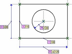
If the parameter described by a Relation is bound to an expression or a variable, then the Relation mark displays both the expression and its current value. The user can edit the expression itself in the same way as its value.
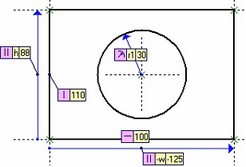
Sometimes, a Relation mark may obstruct working with the model by overlapping a portion of the drawing. To fix the situation, you can delete or hide from display such Relation (how to do it will be described a bit later), or simply move the Relation mark aside.
To move a Relation mark, point the mouse at the Relation icon. Once the cursor changes to ![]() , depress
, depress ![]() and, while holding the mouse button, drag the mark image to the desired position. The moved mark will be connected with the Relation image by a leader line.
and, while holding the mouse button, drag the mark image to the desired position. The moved mark will be connected with the Relation image by a leader line.
You can move not only the relation mark, but also the Relation image that appears as an arrow connecting the 2D element, for which this relation is created, and its parent element. To do this, simply move the cursor to the Relation arrow and click ![]() . After that, the Relation image will rubberband along with the cursor. Move it to the new position and fix by clicking
. After that, the Relation image will rubberband along with the cursor. Move it to the new position and fix by clicking ![]() again.
again.
Creating Relations with the Command "REL: Element Relations"
A special command "REL: Element Relations" serves to create, as well as hide/show and delete existing, Relations:
Icon |
Ribbon |
|---|---|
|
Parameters → Tools → Relations |
Keyboard |
Textual Menu |
<REL> |
Parameters > Relations |
The following options are available in the command automenu:
![]() <*> Create Relations for All Elements
<*> Create Relations for All Elements
![]() <Del> Delete All Relations
<Del> Delete All Relations
![]() <C> Create Relations for selected Elements
<C> Create Relations for selected Elements
![]() <P> Create Relations for parent Elements chain
<P> Create Relations for parent Elements chain
![]() <D> Delete Relations mode
<D> Delete Relations mode
![]() <Esc> Exit command
<Esc> Exit command
There are three ways to create Relations:
1. Automatic creation of Relations for all construction elements in the current drawing. For this, you just need to push the ![]() option after starting the command;
option after starting the command;
2. Manual creation of Relations for individual construction elements with the option ![]() . After calling the option, select the construction elements in the 2D window, for which you need to create relations.
. After calling the option, select the construction elements in the 2D window, for which you need to create relations.
3. Manual creation of Relations for chains of dependent elements with the option ![]() . After calling the option, select the element in the 2D window, which will be the last in the chain. Relations will be created for the specified element through the entire chain of parent elements up to the base ones (those that are independent of other construction elements).
. After calling the option, select the element in the 2D window, which will be the last in the chain. Relations will be created for the specified element through the entire chain of parent elements up to the base ones (those that are independent of other construction elements).
The created Relations will be always shown on the drawing, whether in the command waiting mode or inside any 2D command. Some of the existing Relations can be hidden from display, if you specify in the command properties window, which Relations shall be visible. This is done with the help of flags defining the visibility/invisibility of each Relation type (all flags are enabled by default):
Relations for construction lines:
Parametric Relations – Relations for construction elements that use geometrical parameters, which can be defined by variables. Such geometrical parameters include, for example, an offset line parallel to another line, an angle of a line inclined with respect to another line or to the horizontal, a circle radius etc. The exception is vertical and horizontal lines, for which Relations visibility is controlled by a special flag (see below).
Symmetry – Relations for lines constructed as the symmetry axis for two other lines.
Tangency – Relations for elements constructed with the tangency condition.
Horizontal/Vertical – Relations for vertical and horizontal lines.
Orthogonal – Relations for the lines constructed as perpendicular to other lines.
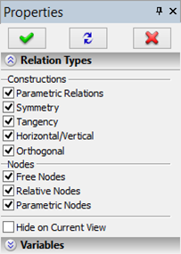
Relations for nodes:
Free Nodes – Relations for the free nodes, meaning those defined by two coordinates - X, Y.
Relative Nodes – Relations for nodes defined by an offset relative to another node.
Parametric Nodes – Relations for nodes having one numerical parameter. Such nodes include the nodes on construction lines (circles, splines, functions etc.), as well as a node relative to another node on a line.
The flags in an additional "Variables" section serve to control the visibility of Relations depending on whether variables were used to define geometrical parameters of those elements (by default, those flags are disabled):
Only Related to Variables. When this flag is enabled, the 2D window will display the Relations only for those construction elements, which were defined using variables.
The list below shows all numerical variables in the current document. An additional flag "Show Hidden Variables" serves to display in this list also the hidden numerical parameters of the current document. Using the list, you can specify the variables that shall be considered when determining which Relations to show. To select a variable, you need to set the flag beside its name (using ![]() ).
).
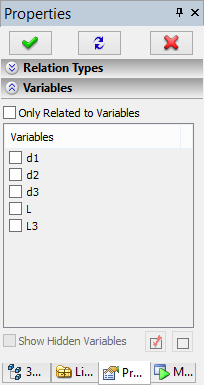
All variables in the list can be quickly marked with the button ![]() . Checks can be cleared off all variables in the list by the button
. Checks can be cleared off all variables in the list by the button ![]() .
.
After exiting the command, the Relations hidden by the above-described flags will stay hidden from the drawing. Nevertheless, they exist in the model. To make them visible, you need to call the "REL: Element Relations" command again and set the respective flags in its property window. You do not need to create Relations anymore in this case.
Hide on Current View. When enabling this flag, all created Relations become invisible in the current 2D window. However, those will be visible in other 2D Windows of the same drawing (if any are open). Just like in the case of using the previously described flags, to alter the relations visibility/invisibility once out of the command, you would have to call it again and change the status of the given flag in the property window.
Relations are deleted with the options ![]() and
and ![]() . When clicking
. When clicking ![]() , all previously created Relations will be automatically deleted. The option
, all previously created Relations will be automatically deleted. The option ![]() is used to delete individually selected Relations. After calling this option you need to sequentially select any Relations to be deleted.
is used to delete individually selected Relations. After calling this option you need to sequentially select any Relations to be deleted.
Managing Relations Visibility outside "REL: Element Relations" Command
You can manage the visibility of created Relations even without calling the command "REL: Element Relations". The "View" toolbar provides the ![]() icon to call the special command "Show/Hide Relations". The effect of this command is same as setting/clearing the "Hide on Current View" flag in the property window of the command "REL: Element Relations".
icon to call the special command "Show/Hide Relations". The effect of this command is same as setting/clearing the "Hide on Current View" flag in the property window of the command "REL: Element Relations".
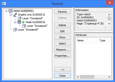
Displaying Relations in the "Info" Command Window
When the "Info" dialog is activated for selected or all model elements, the relation objects are displayed in this dialog in a special way. An existing relation icon is displayed beside the element, to which it pertains.