Sculpt Deformation


Sculpt Deformation |
|
General Information
In the sculpt deformation, the deformation function is defined by displacing the nodes of the regular mesh on one of the faces of the bounding parallelepiped of the deformation area.

The bounding parallelepiped, as in the previously considered deformation type, can be built with respect to the axes of the global coordinate system or additionally-specified LCS.
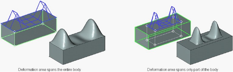
By default, the parallelepiped of the deformation area spans the entire body. If necessary, its dimensions can be modified, thus altering the deformation area. The offset of the faces of the parallelepiped relative to their initial position can be defined by specifying both an absolute and relative value and also by snapping to a 3D point.
The regular mesh is automatically created on a face of the bounding parallelepiped which is selected for creating deformation. Dimensionality of the mesh is specified by the user. Any node of the mesh can be displaced from its initial position by the user-specified value. Several nodes can be selected and moved simultaneously.
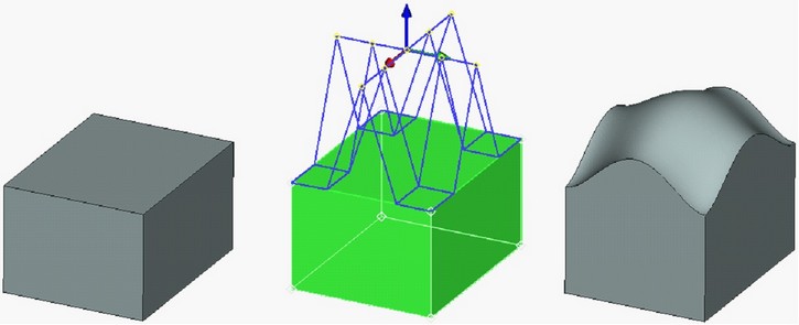
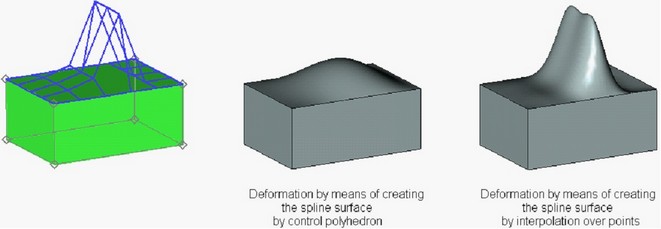
As a result of displacing the nodes of the mesh, the flat face of the bounding parallelepiped is transformed into a space spline surface which forms the required transformation law of the body. The spline surface being formed can be of two types: control polyhedron type (the nodes of the mesh are used for constructing the control polyhedron of the surface) and interpolation type (going directly through the nodes of the mesh).
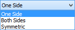
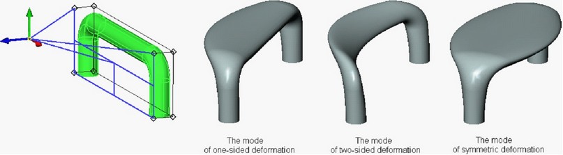
The sculpt deformation has three modes:
●One side – only the nodes located on the selected face of the bounding parallelepiped are displaced;
●Both sides – the nodes located on the selected and the opposite faces of the bounding parallelepiped are displaced. The nodes on the face opposite to the selected one are displaced in the same direction by the same distance;
●Symmetric – the nodes located on the selected and the opposite faces of the bounding parallelepiped are displaced. The nodes on the opposite face are displaced symmetrically with respect to the symmetry plane of the parallelepiped.
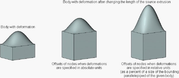
The value of the mesh points offsets from their initial position can be specified both in absolute units – units of model and in relative units – in fraction of length (in percents) of the bounding parallelepiped along the respective axes. The relative coordinates can be used in cases when it is necessary to preserve proportions of the deformed model no matter what changes in the source operations are made. The picture below shows how the deformed model will be modified when changing the length of the source extrusion depending on in which units the offsets of the mesh points have been specified.
A snap to 3D points can be also specified for the nodes of the mesh. In this case the offset is determined by the location of the 3D snap point and does not depend on modification of the deformed body or on units in which the offsets are specified.
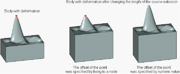
When fixing the node of the mesh to a 3D point, the node's offsets with respect to the selected 3D point can be specified additionally.
Creation of Sculpt Deformation
For creating this type of deformation, the command “3DRC: Sculpt Deformation” is used:
Icon |
Ribbon |
|---|---|
|
3D Model → Special → Deformation → Sculpt Deformation |
Keyboard |
Textual Menu |
<3DRC> |
Operation > Deformation > Sculpt Deformation |
After invoking this command, a user has to:
1.Select the deformed body;
2.Define LCS with respect to which the bounding parallelepiped will be formed (optional step);
3.Define the deformed face of the bounding parallelepiped;
4.Specify the boundaries of the deformation area (of the bounding parallelepiped of the deformation area) (optional step);
5.Specify mesh parameters on the selected face (optional step);
6.Specify the mode of deformation: one-sided, symmetric or two-sided deformation (optional step);
7.Define the desired displacements for the nodes of the mesh;
8.Complete the operation creation by pressing ![]() .
.
Selection of Deformed Body and LCS for Deformation Area Construction
For selecting the deformed body, the following option of the automenu is used:
|
<O> |
Select Body to Deform |
This option is turned on by default upon the entry into the command. The deformed body is selected with the help of ![]() in the 3D window or in the tree of the 3D model. The selected body is highlighted, and the contour of the bounding parallelepiped appears on the screen.
in the 3D window or in the tree of the 3D model. The selected body is highlighted, and the contour of the bounding parallelepiped appears on the screen.
By default the bounding parallelepiped is calculated with respect to the axes of the global coordinate system. It is possible to select another coordinate system for calculation of the bounding parallelepiped with the help of the option:
|
<L> |
Select Source LSC |
After choosing the LCS, the bounding parallelepiped will be automatically reconstructed in accordance with the axes of the LCS.
Cancellation of the selected LCS can be done with the help of the option:
|
<C> |
Cansel LSC selection |
Selection of Deformed Face and Deformation Mode
After specifying the bounding parallelepiped, the user has to indicate the face which will be subject to deformation. To do it, it is sufficient to bring the cursor to the desired face (it will be highlighted) and press ![]() . The option of face selection will become active at this moment in the automenu:
. The option of face selection will become active at this moment in the automenu:
|
<T> |
Select Face |
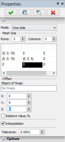
The mesh will appear on the selected face (by default it is a 3x3 mesh). The mesh parameters can be changed in the command's properties window (parameters group “Mesh Size”). The maximum allowable size of the mesh – 20x20.

By default, the deformation is created in the one-sided mode, i.e. only the nodes of the selected face of the bounding parallelepiped are displaced. The mode can be also changed in the command's properties window with the help of the parameter “Mode”. |
|
Modifying Size of Deformation Area
The bounding parallelepiped of the deformation area initially spans the entire body. To modify the size of the deformation area, the following option of the automenu is used:
|
<D> |
Change Deformation Box |
After invoking this option, the command will turn to the mode of modifying the boundaries of the deformation area. Highlighting of the deformed face and the mesh temporarily disappear from the screen. The list of the faces of the deformation area bounding parallelepiped appears in the command's properties window.
The offsets for the faces of the bounding parallelepiped can be specified directly in the 3D window or in the command's properties window (with the help of the list of the faces).
For moving the face in the 3D window, it is sufficient to point at it with the help of ![]() (the selected face will be highlighted) and, without releasing the pressed mouse button, shift the face to the desired position. When selecting the face in the 3D window, it will be automatically highlighted in the list of faces in the properties window. The offset specified for the face will be shown in the entry field of the parameter “Offset”.
(the selected face will be highlighted) and, without releasing the pressed mouse button, shift the face to the desired position. When selecting the face in the 3D window, it will be automatically highlighted in the list of faces in the properties window. The offset specified for the face will be shown in the entry field of the parameter “Offset”.
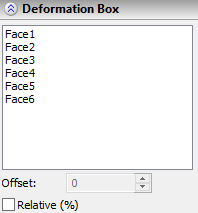
The position of the face of the bounding parallelepiped can be also modified in the properties window just by selecting the face from the list (in the 3D window the selected face will be highlighted in color) and by entering the desired offset into the entry field of the parameter “Offset”.
To specify the offsets of the faces in relative units (relative to the initial size of the deformation area bounding parallelepiped, that is the size of the bounding parallelepiped of the deformed body), set on the flag “Relative Value, %”.
To fix a face to a 3D node, use the option:
|
<Z> |
Set Fixing to Point |
After invoking this option, define a 3D point to which the selected face of the deformation area bounding parallelepiped should be fixed. Any 3D object capable of defining a point (3D node, the vertex of the body, etc.) can be used for specifying this point.
A user can also specify the offsets for the face fixed to a 3D point – in this case these offsets will be relative to the 3D point to which the face is fixed.
To cancel the snap of the face to a 3D point, use the option:
|
<H> |
Cancel Fixing to Point |
After canceling the fixing, the face location does not change. However, the offsets of the face will be subsequently recalculated with respect to the body's overall size and will not depend on the location of the former fixing point for the given face.
For quick cancellation of all modifications of the deformation area, the following option can be used:
|
<W> |
Set Deformation Box by Body Size |
This option cancels all specified offsets for the faces of the deformation area bounding parallelepiped.
To exit the mode of modifying the size of the deformation area, in the automenu turn off the option ![]() .
.
Specifying Offsets of Deformation Mesh Points
Offsets of the mesh points can be specified both in the dialog of the properties window and directly in the 3D window.
For specifying offsets in the 3D window, select successively the nodes (or group of nodes) and with the help of the dragger in the 3D window move them to the desired location.
For selecting one mesh point, it is sufficient to bring the cursor of the mouse to it and press ![]() . The selected node will be highlighted, and the dragger in the shape of the coordinate system will appear at the node. The offset of the node is specified by moving the dragger along one or two axes at once (the work with such dragger is described in detail in chapter “3D Nodes”).
. The selected node will be highlighted, and the dragger in the shape of the coordinate system will appear at the node. The offset of the node is specified by moving the dragger along one or two axes at once (the work with such dragger is described in detail in chapter “3D Nodes”).
There are several ways of selecting simultaneously several mesh points. For example, it is possible to successively select the desired nodes while keeping the key <Ctrl> pressed. In this case, the dragger will be drawn at the last selected node of the group. When moving the dragger, all points of the group will be shifted in the same direction by the same distance.
All nodes lying on the same mesh line can be selected quickly just by pointing at this line with the help of ![]() . While doing that, all nodes lying on the given mesh line will be selected, but the dragger will not appear. To activate the dragger, point with the
. While doing that, all nodes lying on the given mesh line will be selected, but the dragger will not appear. To activate the dragger, point with the ![]() at one of the selected nodes. If while pressing the key <Ctrl>, a user successively defines two mesh lines, all nodes on the defined mesh lines will be selected, etc.
at one of the selected nodes. If while pressing the key <Ctrl>, a user successively defines two mesh lines, all nodes on the defined mesh lines will be selected, etc.
When editing, you can quickly select a rectangular group of points with <Shift>.
In the Interpolation mode, you can add new grid line: hold <Alt> and select one of the existing horizontal or vertical lines in the scene. The deforming principle will not be changed.
For specifying the offsets of the mesh points in the properties window, a table in the parameters group “Mesh Size” is used. Each cell of this table corresponds to one mesh point. The symbol “0” is displayed in the cell if the offset is not specified for the respective node. For the displaced nodes, the specified offsets are shown in the format (X,Y,Z), where X – the node's offset along the X-axis, Y – the offset along the Y-axis, Z – offset along the Z-axis.
To specify offset of any mesh point, in the table select the cell corresponding to the desired node. While doing that, the parameters of the group “Offset” will become accessible for editing below the table. They will define the offsets along the X-axis, the Y-axis and the Z-axis. When modifying the offset values, the node will be moving in the 3D window.
As with the work in the 3D window, it is possible to specify offsets at once for a group of nodes. For selecting several nodes (that is, several cells in the table of nodes), use ![]() +<Ctrl>.
+<Ctrl>.
The units in which the offsets of the mesh points are specified are controlled by the status of the flag “Relative Value, %”. By default it is turned off, and the specified values are absolute (i.е., are measured in units of model). If the flag is enabled, the specified offsets will be recalculated in relative units.
To fixing a mesh point to a 3D point, select the desired node (in the 3D window or in the nodes table in the dialog of the command) and turn on the following option of the automenu:
|
<A> |
Set Fixing to Point |
After activating this option, select a 3D point to which the current node of the mesh should be fixed. The drop down list of this option contains the filters for selecting various 3D objects capable of defining a 3D point.
For the mesh point fixed to a 3D point, it is possible to additionally specify the values of the node's offsets relative to the selected 3D point (with the help of the dragger in the 3D window or in the properties window).
To cancel a fixing of the mesh point to a 3D point, select the desired mesh point (in the 3D window or in the nodes list in the dialog of the command) and invoke the following option of the automenu:
|
<B> |
Cancel Fixing to Point |
After invoking this option, the current mesh point is untied from a 3D point. Note that the offset of the given node does not change at that. The node will remain in the position specified by the 3D point. However, later, when modifying the original model or location of the 3D point, the offsets of the given node of the deformation mesh will be recalculated as if they were specified by numeric values from the beginning.
The type of the formed spline surface (by control polyhedron or by mesh points) is determined by the status of the flag “Interpolation”. When this flag is disabled, the spline surface is created by the control polyhedron, and when the flag is enabled – the created spline surface will go through the nodes of the mesh.
Options in Deformation Operations
In the process of specifying/editing parameters of deformation, the future result of the current operation is dynamically shown in the 3D window. For speeding up the work, the dynamic preview can be turned off by taking off the flag “Dynamic Preview” in the command's properties window.
An additional parameter “Mesh Density” controls accuracy of the mesh used for visualization of the result of the deformation. The increase in the mesh density leads to slower regeneration of the bodies in the scene but increases accuracy of the drawing. |
|
If you disable option Mark body, the body is no longer highlighted in the scene, which simplifies visual perception of the deformed object.

On |
Off |
The Live update option allows to watch deformations of the body in real time. Deactivating the option accelerates recalculation because solid body updating is not required.