3D Nodes


3D Nodes |
|
A 3D node is a T-FLEX CAD element, representing a point in the three-dimensional space. Main use of 3D nodes is as a reference for snapping other three-dimensional objects: additional workplanes, profiles, local coordinate systems, etc. 3D nodes help defining objects necessary for performing operations, such as an extrusion vector, an axis of revolution.
There are several types of 3D nodes. These can be divided into three main groups: nodes based on existing 3D elements, nodes defined in absolute coordinates, and nodes based on 2D nodes.
The display size of 3D nodes on the 3D scene is defined in the command "ST: Set Document Parameters" on the tab "3D>View".
The ways of node creation
To create a 3D node, use the command "3N: Construct 3D Node":
Icon |
Ribbon |
|---|---|
|
Draw → Construct → 3D Node |
Keyboard |
Textual Menu |
<3N> |
Construct > 3D Node |
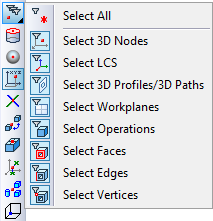
This command helps creating the following types of 3D nodes:
1) Based on existing 3D elements:
- 3D nodes;
- Vertices;
- Local coordinate systems;
- 3D profiles/paths;
- Edges;
- Workplanes;
- Faces;
- Operations;
- At the center of elliptical edge;
- At the center of a sphere or torus;
- At an intersection of elements;
- By shortest distance between elements;
- By faces and offsets;
- At the center of gravity;
2) In absolute coordinates;
3) By two projections.
Using dragger for creating 3D nodes
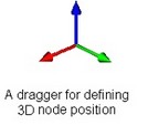
The draggers can be used for creating 3D nodes in the following situations: in absolute coordinates, relative to another 3D node, vertex or a local coordinate system. Draggers can also be used for defining a node relative to the center of an elliptical edge or a surface, which is a sphere or torus. A dragger appears as a coordinate system. It allows moving a 3D node along one axis or simultaneously in two dimensions.
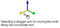
To move a 3D node along one axis, simply move the cursor to one of the node dragger axes. The respective axis will be highlighted in yellow color (by default). Upon clicking ![]() , the selected axis becomes pink (by default), and the dragger starts moving along the selected axis following the cursor. The subsequent clicking
, the selected axis becomes pink (by default), and the dragger starts moving along the selected axis following the cursor. The subsequent clicking ![]() fixes the dragger (and the respective 3D node) in the position of the click.
fixes the dragger (and the respective 3D node) in the position of the click.
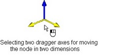
Moving the node simultaneously in two dimensions is done similarly. To do this, simply move the cursor to the dragger and place it between two axes. The axes will highlight. Upon clicking ![]() the dragger starts moving after the cursor in the plane defined by two axes. The subsequent
the dragger starts moving after the cursor in the plane defined by two axes. The subsequent ![]() fixes it in the new position.
fixes it in the new position.
Moving the dragger of the 3D node being created causes update of the node coordinates (offsets) in the property window. Vice versa, modifying the coordinates of a 3D node in the dialog box moves the node dragger.
Main node creation techniques on a 3D element or relative to a 3D element
The following automenu option provides for most common ways of creating 3D nodes based on existing 3D elements:
![]() <S> Create 3D Node on element or relative to element
<S> Create 3D Node on element or relative to element
The option becomes active right after entering the command. To create a 3D node based on a 3D element, simply select the desired 3D element in the 3D scene or model tree. Such a 3D element can be an existing 3D node, a local coordinate system, 3D profile or path, a workplane, operation, face, edge or body vertex. When selecting 3D elements, pay attention to the state of element selection filters in the pull-down list under the option |
|
Creating node based on existing 3D node, 3D vertex or local coordinate system
Creating node based on single connected 3D profile, 3D path, or edge
Creating node based on workplane
Creating node based on underlying surface
Creating node based on operation
When selecting an operation as the parent element, the command switches to the mode of node creation at the center of gravity of the body or a group of bodies, as described below. The selected operation becomes the first body in the group that will be used for constructing the 3D node.
Special ways of creating nodes based on existing 3D elements
Special ways of creating 3D nodes based on existing 3D elements are separated into a special group of options in the automenu, inactive by default.
Creating node at center of elliptical edge or center of sphere or torus
Creating node at intersection of elements
Creating node by shortest distance between elements
Creating node by faces and offsets
Creating node at center of gravity
Creating node at intersection of three planes
Creating node in absolute coordinates
Creating node by two projections
Creating 3D nodes by Grid of Workplanes
Upon creating/editing 3D nodes, in situations, when selection of a 3D point is required, there is a capability of transparent construction of a 3D node by the grid of workplanes (without invoking the “3N: Construct 3D node” command). When the grid is displayed in all operations, in which selection of a geometric point is required, it is possible to select the points at the nodes of the grid of workplanes, and also the points of intersection of paths and planes. In the latter case, at the nodes of the grid a 3D node is automatically created.