Worksurfaces


Worksurfaces |
|
Worksurfaces are auxiliary 3D elements that represent geometrical surfaces of certain type. A cylinder, sphere or torus can be used as such surfaces. The functional purpose of worksurfaces is similar to that of workplanes. Generally, those are intended for carrying 2D objects over to the 3D space. Each worksurface is always related with a parametric region on a page of a 2D drawing. Auxiliary 3D elements, such as 3D nodes, 3D profiles and 3D paths, can be created based on a flat 2D image located on this page. Those elements will be placed on the respective worksurface – a cylinder, sphere or torus.
The main purpose of worksurfaces is creation of auxiliary objects (3D profiles, 3D paths, 3D nodes) for creating parts whose surfaces are curved in two directions: turbine blades, boat propellers, ship hulls, aircraft fuselages.
Main concepts
Worksurfaces are defined parametrically in the special coordinate systems:
- cylindrical;
- spherical;
- toroidal (ring-shaped).
The parametric coordinates are always counted with respect to an orthogonal (Cartesian) coordinate system. (The meaning and the range of the coordinates depend on the surface type.) The particular Cartesian system can be either the world coordinate system, or a specifically selected local coordinate system (LCS).
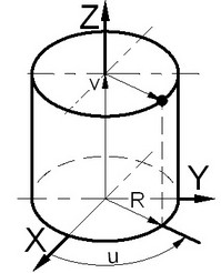
The position of a point in the cylindrical coordinates is defined by three parameters: the radius of the cylinder, the shift along the cylinder axis (Z-axis) and the angle (or the arc length) between X-axis and the radius-vector of the point projection onto the X-Y plane.
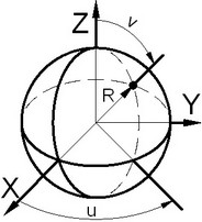
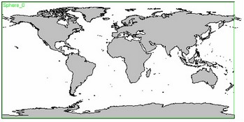
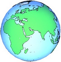
The position of a point in the spherical coordinates is defined by three parameters: the radius of the sphere, the angle between X-axis and the radius-vector of the point projection onto the X-Y plane, and the angle between the point radius vector and Z-axis.
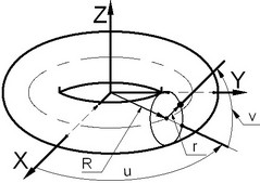
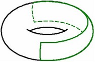
The position of a point in the toroidal coordinates is defined by four parameters: the two defining radii of the torus, the angle between X-axis and the point projection on the X-Y plane and the angle between the point radius vector and Z-axis direction.
The parameters defining the radius of the cylinder, that of the sphere or the two torus radii are called fixed, as those are the same for all points belonging to one surface. This is a constant characteristic of the given surface. The cylinder and the sphere have one fixed parameter – the radius, while the torus – two (the two torus radii).
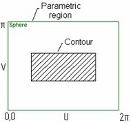
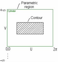
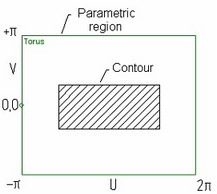
Therefore, the position of a point belonging to a surface of any type is actually defined in a special coordinate system by two orthogonal parameters – the coordinates (U and V). Due to this fact, a mapping can be established between any of the special coordinate systems and a rectangular region on a plane (a parametric 2D region). This 2D region represents an "unfolding" of the surface onto the plane (according to the rules of mapping the UV-coordinates into the Cartesian coordinates for the selected type of surface), playing the same role as the image of the workplane on a page of a 2D drawing. Besides, the 2D region defines the range of the UV-coordinates.
Introducing a parametric 2D region allows working with a surface as if with a common workplane.
Graphic Illustration |
Parametric 2D region |
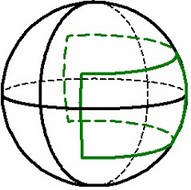
Profile in 3D |
Spherical coordinates
|
U – angle from X-axis (0-2π) V – angle from Z-axis (0-π) R – radius of the sphere |
|
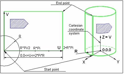
Cylindrical coordinates
|
U – angle from X-axis (0-2π) or arc length counted from X-axis (0-2πR) V - Z-coordinate (-,+) R – radius of the cylinder |
|
Toroidal coordinates
|
U – angle from X-axis (0-2π) V – angle from the vector R in the plane ZOR (-π,+π) R – torus major radius, r – torus minor radius |
|
Data required for creating a worksurface
When creating a worksurface of any type, you need to define:
● The parametric 2D region (a rectangular region in the 2D drawing) – the unfolding onto a plane of the surface being created;
● The fixed parameter value for this surface (the radius of the sphere or cylinder, or the two torus radii);
● The original Cartesian coordinate system (the world coordinate system or an arbitrary LCS), with respect to which the parametric surface coordinates are defined.
Parametric region
The parametric 2D region of a worksurface is defined on one of 2D pages of the current document. The size and position of the parametric region in the drawing units is defined either by the system automatically or by the user (by specifying two 2D nodes as the diagonal corners of the region). The size of this region in the parametric coordinates is always constant, depending on the type of the surface being created (entered as the "ranges" in the table above). The region extents along the Х-axis are mapped onto the allowed range of the parameter U, along the Y-axis – onto V (the reverse configuration is also supported).
In the cases when the position and size of the parametric region are defined by the user (by selecting two 2D nodes), the direction of the worksurface axes is determined by the nodes selection order and position. The diagrams below show the configurations of the UV-axes directions with respect to the order of node selection.
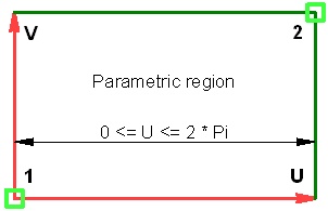
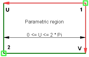
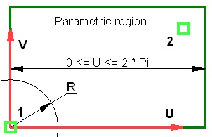
When the parametric 2D region of the worksurface is defined automatically, the axes are always directed as shown on the right-hand-side figure.
In spherical and toroidal coordinate systems, both parameter axes represent angular coordinate values. The exception is the cylindrical coordinate system. Since a cylinder can be "unwrapped" onto a plane without distortions, linear units can be used as cylindrical coordinates. The V-axis units are always linear, while the units of the U-axis can be either angular (the angle between the radius vector and X-axis) or linear (U being the linear distance as measured along the cylinder unfolding).
When using linear units along the U-axis of the cylindrical coordinates, the second 2D node defines only the axes orientation. The size of the parametric region along the U-axis in this case is equal to 2pR, where R is the cylinder radius. The diagram below shows the way of defining the parametric region for a cylindrical surface, when linear units are used in both axes.
When using angular units along the U-axis in cylindrical coordinates, both nodes are used. The linear distance between the two nodes along the U-axis is considered equal to the angular value of 2p. The linear coordinates in this direction will be converted into the angular ones based on this constant.
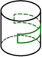
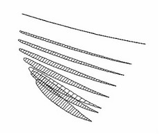
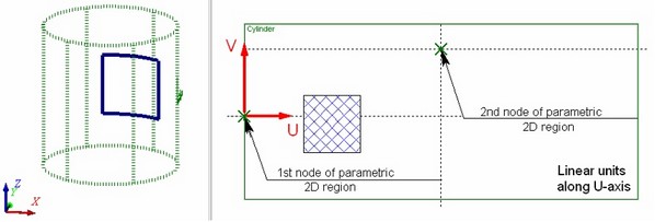
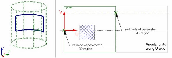
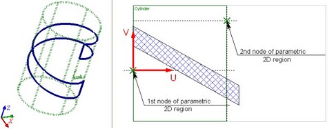
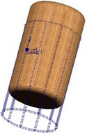
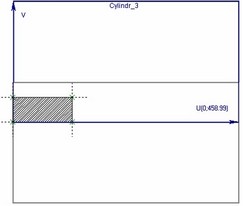
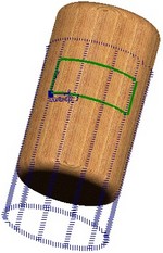
The choice of units along the U-axis – linear or angular – depends on a particular task. If the 2D construction to be carried over on a cylindrical worksurface is described in linear units, then it may be more convenient to use linear units along the both axes of the cylindrical coordinates. In this case, the 2D construction will be carried over to the 3D space preserving all relations between the construction elements. Use of angular units in such a situation will cause distortions in the transition from 2D to 3D. As in illustration, consider a simple example of creating a 3D profile on a cylindrical worksurface using a 2D hatch of square shape. One can easily see that the profile shape is far from square when using the angular units along the U-axis. Meanwhile, when using the linear units, the 3D profile matches the shape of the hatch.
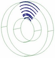
Use of the angular units along the U-axis of the cylindrical coordinate system makes sense only in the cases when the original 2D constructions are described using angular values. For instance, in the following example, the original 2D data for creating a model of a heat exchanger are defined in the angular values on the surface of a cylinder. Use of angular units helps easily getting the desired result (provided that the boundaries of the parametric region of the worksurface were defined correctly).
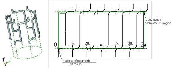
To be comfortable when working with angular units, use the following rule. The distance between the 2D nodes along the U-axis must be set so that the total width of the parametric region along the U-axis (that is, the respective distance between the nodes defining its boundary) is a multiple of 360 (in degrees), or 2p (when using radians).
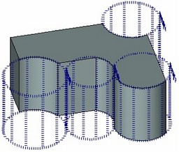
When working with worksurfaces of any type, keep in mind the following. Any of the worksurfaces are periodic in one or both UV-parameters. Therefore, a parametric surface has cycles in the direction in which it is periodic. The diagram below shows periodicity of a parametric 2D region for spherical and toroidal surfaces.
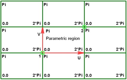
In the case of a cylindrical surface, the parametric 2D region cycles only along the U-axis.
The Fixed Parameter and the Cartesian Coordinate System of the Worksurface
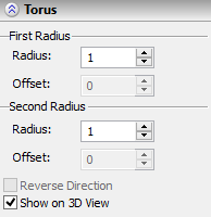
A fixed parameter value (two parameters – in the torus case) is defined with a numerical value. When creating a worksurface by an existing geometrical surface, the fixed parameter value is determined by the specified offset along the radius of the source geometrical surface.
The position of the worksurface in space is defined by selecting a Cartesian coordinate system. The parametric coordinates will be counted with respect to the system. An arbitrary LCS can be selected as such a system. If no local coordinate system is specified, the world coordinates are used.
When constructing a worksurface by an existing geometrical surface, the coordinate system of the source geometrical surface is used as the Cartesian coordinate system.
Introduction to Worksurfaces
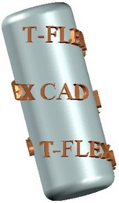
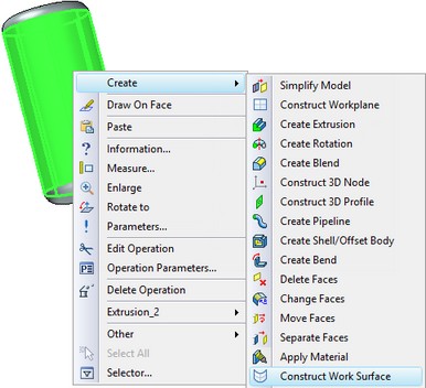
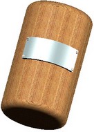
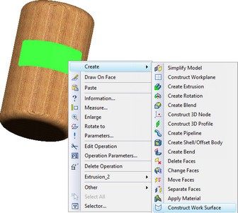
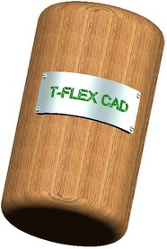
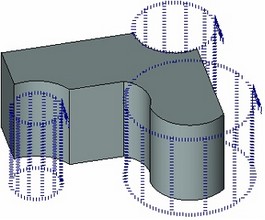
To understand how worksurfaces are created and used, let's review a brief example. Suppose, we need to wrap a text on a cylindrical body face. To do this, let's create a cylindrical worksurface coinciding with the surface of that cylindrical body face. Then it is possible to create a 2D element-text on that surface, and use it to create a 3D profile and a text-like looking body. To create a worksurface, select a cylindrical face of the source body in the 3D window and call its context menu. In the context menu, select the command “Create/Construct Worksurface”.
As a result, the command will be launched, “3SU: Construct Worksurface”. Upon entering the command, the cylindrical face will be automatically selected. To create the worksurface, just click ![]() . As a result, a cylindrical worksurface will be created, which coincides in the radius and position in the space with the source face, or, rather, with its geometrical surface.
. As a result, a cylindrical worksurface will be created, which coincides in the radius and position in the space with the source face, or, rather, with its geometrical surface.
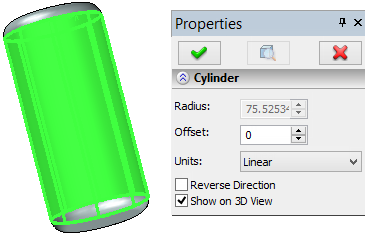
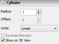
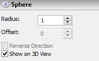
The command's properties window displays the parameters of the surface being created. Those do not need to be changed.
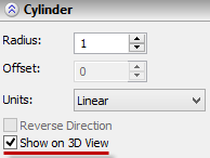
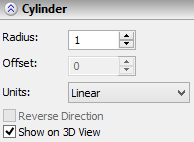
The “Offset” parameter defines the difference between the source face radius and that of the surface being created. The required “0” value is already set by default.
The “Units” parameter defines, what units will be applied along the U-axis. The default setting “Linear” should also be left unchanged.
By now the worksurface is created. Now we need to create the 3D profile-text on it. To do that, select the created surface and call its context menu by right-clicking ![]() . In the menu select the command “Draw On Workplane”.
. In the menu select the command “Draw On Workplane”.
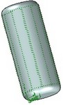
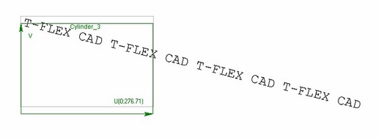
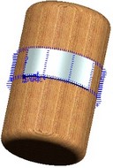
A separate window will open with the 2D drawing page, corresponding to the selected worksurface. A box will be marking the parametric 2D region of a worksurface on the page. Let's create the required text on the 2D page. Finish drawing on the active worksurface by clicking ![]() on the control panel of the active workplane (actually, a surface in this case). Upon leaving the mode of drawing on the active worksurface, a 3D profile will be automatically created based on the 2D text.
on the control panel of the active workplane (actually, a surface in this case). Upon leaving the mode of drawing on the active worksurface, a 3D profile will be automatically created based on the 2D text.
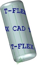
What is left is to extrude the 3D profile to the required height and perform a Boolean addition of the resulting text and the source cylinder.
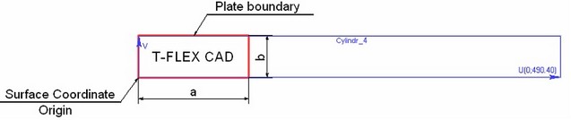
Let's see another example. In it, we need to apply a text on a cylindrical-shape plate while maintaining a specified offset distance from the plate borders. In this example, two worksurfaces will be used. We will construct the first one by the cylindrical face of the source body. On it, let's create the 3D profile of the plate contour. We will construct the second worksurface by the outer face of the plate. The 3D profile-text will be created on the latter worksurface.
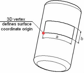
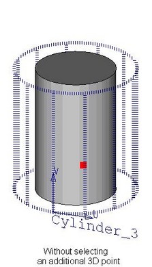
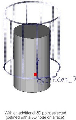
The difference of this example from the previous one is that in this case we need to know how precisely the worksurfaces and their source faces are positioned relative to each other. Otherwise, it will be impossible to precisely position the plate on the cylindrical body, and the text – on the plate. To precisely position the worksurface, one can use an additional 3D point. The surface coordinate origin will be placed at that point. Let's create a 3D node on the face of the source body where the lower-left corner of the plate shall be positioned. Next, as in the previous example, we need to select a cylindrical face of the source body, call its context menu and launch the command “Create/Construct Worksurface”.
We again will leave unchanged the default parameters of the worksurface being created. But, before confirming the surface creation, we will enable the automenu option:
![]() <1> Select starting point
<1> Select starting point
Using this option, we will select the 3D node created earlier. The surface coordinate origin will be positioned where the node projects (maps) on the surface. After selecting the 3D node, the worksurface creation can be finilized by clicking ![]() . After that we will select the worksurface and call from its context menu the command “Draw On Workplane”. As in the previous example, after calling the command, a separate window will open with the 2D drawing page corresponding to the selected worksurface. A box on the page will be marking the parametric 2D region of the worksurface. The worksurface coordinate origin (the lower-left corner of the box) corresponds to the 3D node that defines the lower-left corner position of the would-be plate.
. After that we will select the worksurface and call from its context menu the command “Draw On Workplane”. As in the previous example, after calling the command, a separate window will open with the 2D drawing page corresponding to the selected worksurface. A box on the page will be marking the parametric 2D region of the worksurface. The worksurface coordinate origin (the lower-left corner of the box) corresponds to the 3D node that defines the lower-left corner position of the would-be plate.
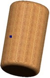
By accepting the lower-left corner of the box as the base point, let's create the necessary 2D constructions to create the plate contour. To create the 3D profile, we need to apply graphic lines and/or hatch. Finish working in the mode of drawing on the active worksurface by clicking ![]() on the control panel of the active workplane. Upon exiting the mode of drawing on the worksurface, the plate's 3D profile will be automatically created. The plate body is created by extruding the resulting 3D profile.
on the control panel of the active workplane. Upon exiting the mode of drawing on the worksurface, the plate's 3D profile will be automatically created. The plate body is created by extruding the resulting 3D profile.
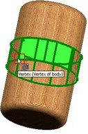
To create text on the plate, we will construct a second worksurface. The construction will be similar to the previous cases. To define the surface coordinate origin, select one of the vertices (the lower-left one) of the plate's upper face.
After creating the second worksurface, we will go into the mode of drawing on it (the command “Draw On Face” in the surface's context menu). On the worksurface page, mark the plate boundaries. After that, apply 2D text at the desired position on the plate.
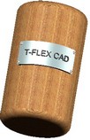
Next, the 3D profile on the worksurface is created based on the 2D text. The profile is extruded, and a Boolean addition with the plate body is performed. In the described example, we relied on a 3D point selection as the worksurface origin to precisely position the 3D profile contour on the worksurface. The same goal could be achieved using a different method. Working in the mode of drawing on the active worksurface (the command “Draw On Workplane” in the context menu) is mostly analogous to working in the respective mode on a workplane. The only difference is that one can draw on a workplane both in 2D window and directly in the 3D window. For a worksurface, only the mode of drawing in the 2D window is available. Besides that, all other functions of this mode are supported for a worksurface, including the capability of projecting (mapping) a 3D point on the active plane/surface.
In our example, one could have skipped selecting additional 3D nodes as the origin for worksurfaces, but rather have them mapped in the drawing-on-surface mode. After that, it is possible to create all underlying construction for the 3D profile contours based on the created 2D nodes-the projections.
Methods of creating worksurfaces
There are three methods to create a worksurface:
1. Creating a worksurface by an existing geometrical surface of the respective type (a surface underlying a face, 3D profile, another worksurface). This method was used in the aboveDescribed examples.
2. Creating an arbitrary worksurface (that is, without being based on existing geometrical surfaces in the 3D model) in the 3D window.
3. Creating an arbitrary worksurface based on 2D constructions (in the 2D window).
Worksurface based on existing geometrical surface
Worksurface creation by an existing geometrical surface is performed in the 3D window. To define the source data, select a 3D object related to the intended geometrical surface. As a result, a worksurface is created that coincides with the source geometrical surface.
Additionally, you can specify an offset amount (two offsets for a torus), which defines the difference between the source and target surface radii. In this case, a worksurface will be created as an equidistant (offset) to the source geometrical surface.
The source geometrical surface coordinate system is used as the Cartesian coordinate system for the created worksurface. The coordinate system position for the worksurface being created can be adjusted by selecting an additional 3D point. The point will determine the worksurface coordinate system origin (that is, the X-axis direction of the Cartesian coordinate system). Two 3D points are defined for a spherical worksurface – first determining the X-axis direction, and the second adjusting the Z direction (and, therefore, the Y-axis).
A separate 2D page of the “Workplane” type is automatically created for a constructed worksurface. The page's format frame size is determined automatically by the size of the 3D object that was used to define the source geometrical surface. The parametric 2D region of the worksurface is also created automatically. Its size is equal to the size of the page format frame.
The created worksurface is by default displayed in the 3D window.
Arbitrary Worksurface
An arbitrary worksurface is also created in the 3D window. To create a worksurface by this method, you need to specify the type and the radius (two radii for a torus) of the surface being created.
Additionally, you can specify an LCS, relative to which the parametric coordinates of the worksurface will be counted.
As in the previous method, a separate 2D page of the “Workplane” type is automatically created for such worksurface. The dimensions of the page format frame and the parametric 2D region worksurface are automatically determined by the system.
Worksurfaces of this type are also displayed in the 3D window by default.
Worksurface based on 2D constructions (in 2D window)
Creation of a worksurface of this type is done in the 2D window, on an already existing drawing page of any type. To create the surface, you need to define the boundaries (two diagonal corners) of its parametric 2D region. The region boundaries are defined using two 2D nodes. The position and the order of selecting the 2D nodes determine the direction of parametric axes of the worksurface. Besides that, the radius is to be defined (two radii for a torus) of the surface being created.
Additionally, you can specify an LCS, relative to which the parametric coordinates of the worksurface will be counted.
A worksurface of this type can be created on a 2D page that is already related with other worksurfaces or planes. In this case, the boundaries of the parametric 2D region are used by the system to automatically match the 2D elements found on this page, with the respective worksurface/plane (when creating 3D elements – 3D profiles, 3D paths).
If several worksurfaces/planes are related to a 2D drawing page, those cannot be activated.
Rules of creating worksurfaces
To create a worksurface, use the command "3SU: Construct Worksurface".
Icon |
Ribbon |
|---|---|
|
3D Model → Construct → Worksurface |
Keyboard |
Textual Menu |
<3SU> |
Construct > Worksurface |
Upon calling the command, the following options are available in the automenu:
![]() <S> Select Face
<S> Select Face
![]() <1> Spherical coordinate system
<1> Spherical coordinate system
![]() <2> Cylindrical coordinate system
<2> Cylindrical coordinate system
![]() <3> Ring-shaped coordinate system
<3> Ring-shaped coordinate system
The first option – ![]() – serves to construct a worksurface by an existing geometrical surface.
– serves to construct a worksurface by an existing geometrical surface.
The other three options – ![]() ,
, ![]() and
and ![]() – are used to construct either an arbitrary worksurface in the 3D window or a worksurface based on 2D constructions (in the 2D window). How a worksurface will be created depends on where the “3SU: Construct Worksurface” command call originated – from the 3D window or from the 2D window.
– are used to construct either an arbitrary worksurface in the 3D window or a worksurface based on 2D constructions (in the 2D window). How a worksurface will be created depends on where the “3SU: Construct Worksurface” command call originated – from the 3D window or from the 2D window.
Creating worksurface by an existing geometrical surface
To create a worksurface by an existing geometrical surface, use the option ![]() . It is turned On by default. With the option enabled, select a 3D object in the 3D window or in the model tree, suitable to define a surface of the cylindrical, spherical or toroidal type. This could be a face of the respective type, a 3D profile, or an existing worksurface.
. It is turned On by default. With the option enabled, select a 3D object in the 3D window or in the model tree, suitable to define a surface of the cylindrical, spherical or toroidal type. This could be a face of the respective type, a 3D profile, or an existing worksurface.
After selecting the source 3D object, the system will automatically determine what-type worksurface will be created. The command's properties window will have the dialog to define parameters of the given worksurface. Depending on the type of the created worksurface, you can define the values of one or two offsets in the properties window. The offsets determine the difference between the radius of the source geometrical surface and the radius of the worksurface being created.
Original direction of worksurface coordinate axes corresponds to direction of the parent surface. “Reverse Direction” flag in the Properties dialog box will reverse direction of both axes.
Additionally, the option is available in the automenu to select a 3D point defining the worksurface coordinate origin:
![]() <1> Select starting point
<1> Select starting point
When creating a spherical worksurface, yet another option will be available in the automenu – to define the second 3D point to adjust the Z- and Y-axis direction of the Cartesian coordinate system::
![]() <2> Select Pole point
<2> Select Pole point
A 3D point (3D points) selection can be canceled with the option:
![]() <D> Cancel selection of points setting surface orientation
<D> Cancel selection of points setting surface orientation
Creating an arbitrary worksurface (in the 3D window)
To create a worksurface of this type, you must call the command “3SU: Construct Worksurface” from the 3D window. After entering the command, you need to specify the type of the surface being created, by selecting the desired automenu option (![]() ,
, ![]() or
or ![]() ).
).
After selecting the surface type, the command will go into the mode of creating the worksurface of the selected type. Define the radius of the surface being created in the command's properties window (two radii for a torus). The surface creation can be completed right after defining the radius (radii), by clicking ![]() (in the automenu or in the command's properties window).
(in the automenu or in the command's properties window).
To define an LCS, relative to which the parametric coordinates of the worksurface will be counted, use the option:
![]() <L> Select target LCS
<L> Select target LCS
The option to cancel a local coordinate system selection is:
![]() <D> Eliminate target LCS
<D> Eliminate target LCS
The system will automatically define the parametric 2D region of the worksurface being created (on a separate drawing page of the “Workplane” type). If necessary, you can manually define the boundaries of the parametric 2D region of the worksurface being created, using the nodes on the same or another 2D page. To do that, use the same options as when creating a worksurface based on 2D constructions.
Creating an arbitrary worksurface based on 2D constructions (in the 2D window)
To create a worksurface of this type, you need to call the “3SU: Construct Worksurface” command from the 2D window. Upon entering the command, just like in the previous case, you need to specify the type of the surface being created (the option ![]() ,
, ![]() or
or ![]() ).
).
After that, you need to define the parametric 2D region of the worksurface being created. If there are no worksurfaces or planes on the current 2D page, then the system will select the region boundaries automatically according to the page format frame size. If, on the other hand, the current drawing page is already related with worksurfaces or planes, or if you are not satisfied with the system choice, define the boundaries of the parametric 2D region by selecting two 2D nodes with the options:
![]() <F> Select Node as origin of parametric region
<F> Select Node as origin of parametric region
![]() <S> Select Node as second border of parametric region
<S> Select Node as second border of parametric region
The start and end points should not coincide. Otherwise, it will be impossible to determine the orientation of the U and V axes.
By default, the range along the Х-axis of the parametric region is mapped onto the range of U parameter, the Y-axis – onto V. This can be changed by the option:
![]() <3> Shift coordinate axes
<3> Shift coordinate axes
The fixed parameter value of the worksurface being created (the surface radius) is defined in the command's properties window.
If the worksurface is to be created relative to a local coordinate system, then you need to use the option:
![]() <L> Select target LCS
<L> Select target LCS
To cancel a local coordinate system selection, use the option:
![]() <D> Eliminate target LCS
<D> Eliminate target LCS
The visible boundaries of a worksurface on the drawing are by default aligned with the defined boundaries of the parametric 2D region. The visible boundaries can be modified with the options:
![]() <B> Define Workplane borders
<B> Define Workplane borders
![]() <Tab> Switch Workplane borders
<Tab> Switch Workplane borders
![]() <K> Eliminate borders
<K> Eliminate borders
These options work in the same way as those provided for common workplanes.
By default, a created worksurface of this type will not be displayed in the 3D scene. To make it appear in the 3D window, enable the “Show on 3D View” flag in the command's properties window.
You can finalize worksurface creation by clicking ![]() (in the automenu or in the command's properties window).
(in the automenu or in the command's properties window).
Worksurface Representation in 3D View
It is possible to control the visibility of the working surface by the special flag “Show in 3D View” available in parameters dialog box when creating/editing a worksurface. By default this flag is turned on, that is to display the worksurface in 3D view. When flag is turned off the worksurface will be not shown in 3D view.