Model Separation Check


Model Separation Check |
|
This command serves for checking, whether an injection or die-cast mold used for making the model part is separable.
The command allows finding the faces of the regions preventing the mold from parting. Additionally, the faces are highlighted, whose taper angle with respect to the selected direction is less than specified.
The command "QS: Check Model Separation" is called via:
Icon |
Ribbon |
|---|---|
|
Measure→ Geometry analysis → Model Separation Check |
Keyboard |
Textual Menu |
<QS> |
Tools > Geometry Analysis > Model Separation Check |
Upon entering the command, you need to specify the direction of separating the mold. To select a direction-defining element, use the option:
![]() <D> Click to select direction
<D> Click to select direction
When using this option, you can select faces, edges, 3D profiles, workplanes and coordinate systems.
To define the direction by specifying two 3D points, use the options:
![]() <S> Select first Vertex or 3D Node
<S> Select first Vertex or 3D Node
![]() <E> Select second Vertex or 3D Node
<E> Select second Vertex or 3D Node
For point selections, you can use 3D nodes, vertices, edges, coordinate systems, sphere or torus faces.
Upon choosing the direction, you need to select the operation, whose faces will be analyzed. To select an operation, use the option:
![]() <B> Select source 3D operation
<B> Select source 3D operation
Select all operations in the scene using the option:
![]() <A> Select all operations
<A> Select all operations
To cancel an operation selection, you need to select it once again.
To cancel selection of all operations, use the option:
![]() <U> Cancel selection
<U> Cancel selection
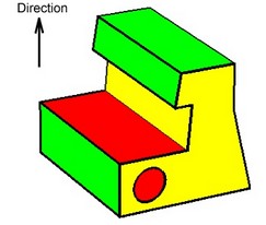
Upon completing the check, the operation's faces change in color. By default, highlighted red are the faces of the regions preventing the mold from parting. The yellow color marks the faces, whose taper angle with respect to the selected direction is less than specified. The green marks the faces that are sufficiently tapered with respect to the selected direction and do not prevent the mold from parting.
If multiple bodies are selected simultaneously, the system will run the separation check on all bodies together as if it was one part. Therefore, the results of checking several bodies separately and together will be different.
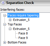
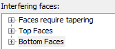
Besides the colored rendering in the 3D window, the check results are displayed in the "Interfering faces" pane. It contains overlapping faces (that prevent the part from ejecting) and faces with insufficient draft. The core and the cavity faces are also specified here. The core and the cavity faces – not overlapping faces with sufficient draft that ensures that the part ejects properly from the tooling. These faces define the mold working region.
If you expand the list of reports and click the name of a problematic face, the face will be highlighted in the 3D window.
If the "Keep selection" flag is set, then, upon leaving the command, the highlighted faces will stay selected. This is done for convenience. The parameter "Minimal slope" sets the minimum permissible taper angle of the faces with respect to the selected direction.
![]()