Setting Common Parameters of System Elements


Setting Common Parameters of System Elements |
|
Each T-FLEX CAD system element, whether a construction or a graphic one, has its own set of parameters that the user can define and modify. In particular, the color, level and layer parameters are present in each set of parameters. Defining and using these parameters will be described here so not to repeat the description for each element.
Element color
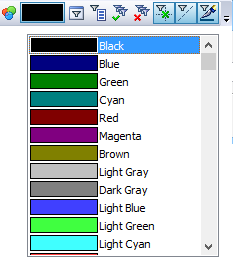
Each element has a color. The parameter dialog includes the input box "Color:".
![]()
This box shows the color used for displaying the given element of the model. The color can be changed by selecting from the list. An element color can also be set using the system toolbar. Setting colors via the system toolbar is available in creation and editing commands.
You can select color from the catalog of colors. Use special button ![]() next to the drop-down list of standard colors in the properties dialog to open appropriate color selection dialog.
next to the drop-down list of standard colors in the properties dialog to open appropriate color selection dialog.
Also you may use appropriate button ![]() in the system toolbar to open convenient color selection dialog.
in the system toolbar to open convenient color selection dialog.
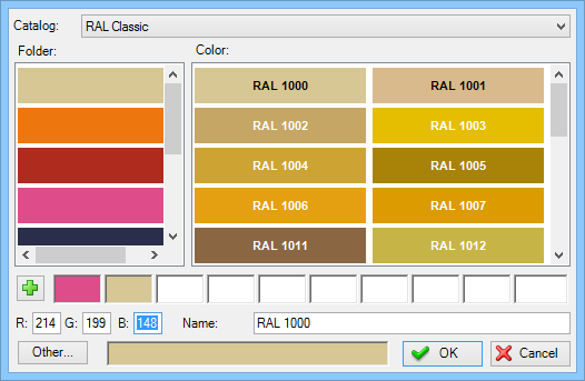
Color catalog contains a set of pages (the list on the left) containing colors. Color is defined as RGB components and name.
Besides the list of colors the dialog contains 10 selected colors, which user may add using them to have for faster and direct access.
Each color catalog is stored in a separate file with the .acb extension. To edit a color catalog you can use any text editor, or one of the editors of available for working with .acb file format. By default, available catalogs of colors are located in system folder Program/ColorBooks. You can change the path for searching catalog of colors at "Folders" tab of "Customize | Options" command dialog.
Element Layer
A layer is a parameter of any drawing element. It defines the element association with a particular group of the model elements.
The user can define the layer name for each system element to belong to. A layer name is a string of up to 20 text characters. An element layer can also be set on the system toolbar.
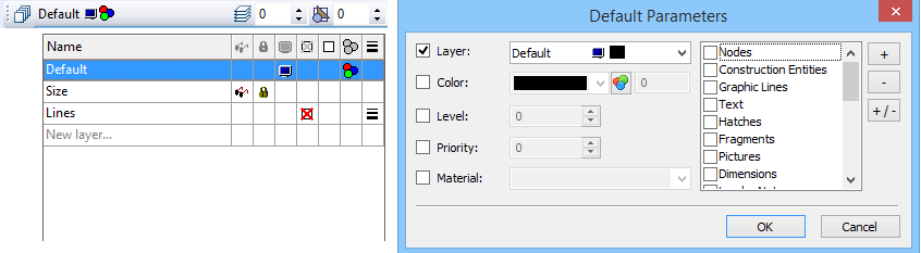
Drop-down part of the control is resizable. The list can be sorted according to various parameters of layers. Clicking an icon can modify layer parameter without leaving the current command. The list has item "New Layer ...» which allows you to create a new layer without exiting the command and to make it active.
Layer parameters can be created, deleted and modified using the command "QL: Configure Layers":
Icon |
Ribbon |
|---|---|
|
3D Model → Style → Layers |
Keyboard |
Textual Menu |
<QL> |
Customize > Layers |
After calling this command the dialog window “Layers” appears. In the window of the given dialog box the list of the layers existing in the given document and their parameters are shown. Under this list there are fields for assigning parameters of the layer and buttons for performing different actions with the fields.
The button [New] creates the new layer in the document. After pressing this button the system asks to give a name to the created layer.
The button [Delete] removes unused layer (it becomes available only upon selecting from the list the layer marked with the sign ![]() ). The button [Rename] allows assigning the new name for the layer selected from the layers list.
). The button [Rename] allows assigning the new name for the layer selected from the layers list.
The [Information] button allows to display the list of objects located on the selected layer.
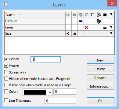
For changing parameters of any layer it is necessary to select it from the list of the layers and set on/off the required flags under the list. You can also set parameters by clicking on the corresponding icon field.
By entering layer parameters you define the properties of the elements belonging to this layer. You can select several layers simultaneously and set parameters for them all.
The following parameters can be defined for each layer:
Hidden. A layer can also be assigned invisible property by using a variable. The variable can have two values: 0 – the layer is visible, and 1 – the layer is invisible.
The variable values different from 0 and 1, are processed by the system as follows: the fractional part is dropped, and the resulting number is matched with 0. If matching, the layer will be visible, otherwise – invisible.
Frozen. When set, no element on this layer will be allowed for selection during element creation and editing.
Screen only. When set, all elements on this layer will be displayed on the screen only, but will not be printed, plotted or exported.
Hidden when model is used as a Fragment. When set, the elements on this layer will not be displayed when the drawing is used as a fragment.
Visible only when model is used as a Fragment. When set, the elements on this layer will only be displayed when the drawing is used as a fragment of an assembly.
Color. When set, all elements on this layer will be displayed in the specified color after the redraw. The color is selected from the color menu.
Line thickness. Upon enabling this flag, the same thickness will be set for all graphic lines in the given layer.
Element level
Each model element is assigned a level. The level of an element is an integer. It defines whether the element will be displayed on screen after the redraw. In other words, it defines the element visibility.
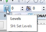
The level value can be within the range from -126 to 127. Each element level is connected with the system element visibility range that is set in the command "SH: Set Levels":
Icon |
Ribbon |
|---|---|
|
3D → Style → Levels |
Keyboard |
Textual Menu |
<SH> |
Customize > Levels |
After calling the command, a dialog box comes up for specifying the ranges of element levels.
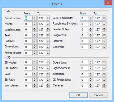
The level visibility range is defined by two numbers in the range from -126 to 127 for each element type. An element visibility upon redraw is defined in the following way:
If the element level value is within the range defined for this type of elements, then the element will be displayed upon redraw.
If the element level value is outside the range defined for this type of elements, then the element will not be displayed upon redraw.
An element level can be defined by a constant, variable or expression.
Advanced usage of element levels in a drawing requires knowledge of working with variables and the command "V: Edit Variables". Therefore, continue studying level setting after gaining the required knowledge.
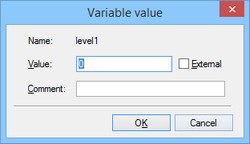
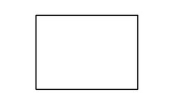
When using a variable for defining a level, enter the variable without braces, for example, LEVEL1 After exiting the parameters dialog box of the given element, another dialog box will come up on screen for setting the value of the variable LEVEL1. Using a variable as an element level allows modifying the way in which the drawing is displayed depending on specific conditions. As an example, create a drawing shown on the following diagram. Set the level of the rectangle diagonals using the variable "A". Set the value of the "A" variable equal to "1". In the command "SH: Set Levels" set the visibility range for the graphic lines from 0 to 127. In the variable editor create a variable "B" with the initial value "1". Enter the following expression in the variable editor for "A": "B == 0?-1:1". |
|
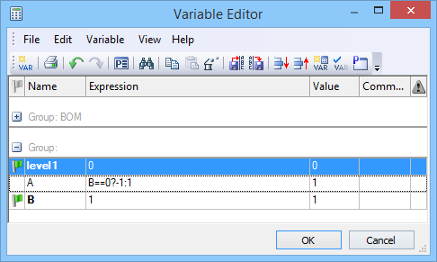
Thereafter, set the value of "B" first equal to "1", and then "0".
With the first value, the created line will be present on screen, while absent with the second value.
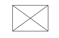
Thus, using variables as levels of various elements, you can create different variations of the same drawing.
Element priority
When creating assemblies, especially, in engineering industry, it is often necessary that one element be drawn on top of others. This behavior is easy to realize using parametric fragments, hidden line removal, and an additional special parameter of graphic elements – the priority.
The fact is, the model elements are drawn on the screen or other graphical devices in a certain order. This order normally corresponds with the element types and the order of element creation. However, this order can be changed using priorities.
A priority, just like a visibility level of an element, is an integer from -126 to 127, which can be specified by a variable value or an expression. The order of drawing elements follows the rule: elements with lower priority are drawn before elements with higher priority. Therefore, an element with a high priority "obstructs" the elements drawn earlier. For fully benefiting from the hidden line removal functionality, the system provides a special attribute of the hatch contour: "Use for hidden line removal". When this attribute is turned on, the area of the hatch is filled with the background color. Therefore, using priorities and special hatches allows creating assemblies using overlays.
An example of using hidden line removal could be any assembly of co-axial parts, created from fragments. In this case, the fragment parts are created without hidden line removal required in the assembly. Simply set their correct priorities when assembling.
Using this method helps significantly speed up the process of creating assembly models and minimizes the necessity for editing elements when modifying the assembly model parameters.