Saving Textual Drawing Information


Saving Textual Drawing Information |
|
While working with T-FLEX CAD, you can create text documents (files) containing various information about a drawing or a model:
● A system of drawing variables, with the respective values and defining expressions;
● A report on variable modifications, including those used in animation;
● Information about geometrical parameters of certain drawing elements;
The saved information about drawing parameters can be used for preparing accompanying documentation or as input data to other applications.
Saving information about drawing variables to file
One way to store drawing variables in an external file is by using the command "WP: Save Model Parameters":
Keyboard |
Textual menu |
Icon |
|---|---|---|
<WP> |
|
|
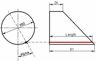
This command allows saving to an external file the values, expressions and comments for all or specifically external drawing elements, at user's preference. The data is written using a specific format:
LD = 110 /* 110 ; Part length: from 60 to 100 1 hole, from 100 to 110 2 */
$vt1 = "Bushing" /* LD>100?"Bushing":"" ; */
HD = 50 /* 50 ; Height of machined part (20-60) */
UGL = 10 /* 10 ; Surface slope angle (0-10) */
lo = 27.5 /* LD<=100?LD/3:LD/4 ; Distance to hole (do-LD/2) */
do = 7 /* 7 ; Diameter of hole (3-15) */
l01 = 97.5 /* lo<LD/2?(lo+15+LD/2):(2*lo+15) ; */
l1 = 131 /* l01>LD+21||LD>100?(LD+21):l01 ; */
ld = 35 /* l01>LD+21||LD>100?(LD-l1+56):LD+20 ; */
$vt2 = "Bushing 2" /* LD>100?"Bushing 2":"" ; */
$vint = "Screw" /* LD>100?"Screw":"" ; */
The information saved in this way can be used in other T-FLEX CAD documents via the command "RP: Load Model Parameters":
Keyboard |
Textual menu |
Icon |
|---|---|---|
<RP> |
|
|
Working with the commands "WP: Save Model Parameters" and "RP: Load Model Parameters" is fully analogous to working with export/import commands of the variable editor, which is described in details in the chapter "Variables".
If you need to save information about values of the drawing variables in an arbitrary form, it might be more convenient to use the report creation mechanism. A report is a text document that is saved in an external file. A report can include an arbitrary text containing values of the drawing variables. The contents of the information saved in an external file is determined by the report template defined in the T-FLEX CAD document. The template text usually includes document variables. At the time of saving the report to a file, the actual values may be written instead of variables. A report can be saved by a user request, or a the time of saving the entire document. Multiple report templates can be created in a T-FLEX CAD document.
Reports can be created while running animation within the command "AN: Animate Model". In this case, the report file will be appended at each animation step with the contents of the template filled with the variable values corresponding to the current step of the animation.
Creating report
To handle reports, use the command "REP: Create Report":
Icon |
Ribbon |
|---|---|
|
Tools → Special Data → Report |
Keyboard |
Textual Menu |
<REP> |
Tools > Special Data > Report |
Upon entering the command, a dialog box appears for handling report templates. If the document already contains templates, one of those will be opened in the dialog window. If no template exists in the document, the dialog window will be empty. In this case, the only accessible button will be [New], allowing to create a new report template.
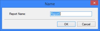
Upon clicking the [New] button, a window appears, in which you need to specify the name of the template being created. The preset default offers the name "Report" with the respective enumerator suffix. Upon clicking [OK], an empty report template will be opened in the command's dialog window.
The name of the opened template appears in the "Name" parameter. Using the same parameter, you can open another template by selecting its name from the list. The selected template name can be modified using the [Rename] button.
Once a template is opened, you can view, define and edit its contents and properties.
The contents of the report template is displayed in the preview pane located at the bottom part of the command's dialog. It appears as plain text usually containing the document variables. The names of variables shall appear in the text within braces. The template contents can be edited directly in the preview pane, using context menu commands, or in a separate text editor window. To access the editor window, use the button [Edit…].
The "Preview" checkbox at the bottom of the command window allows viewing the report in the command's dialog pane exactly as it will be written to a file (with or without substituting variable values, depending on property settings defined for the report template).
The method of storing the report is described by the following group of parameters:
Output Path. This parameter defines the file name for saving the report. The button ![]() allows browsing for another file.
allows browsing for another file.
Auto Save. With this flag set, the report will be automatically saved each time the drawing is saved.
Substitute variables. Defines the method of writing variables to the report. When the parameter is set, the actual current values will be substituted for the variables in the text. When the parameter is turned off, the contents of the template will be written to the report files without replacing variable names by values.
To delete the current template from the document, use the button [Delete]. Upon clicking the button, you would need to confirm the deletion.
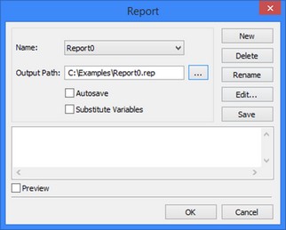
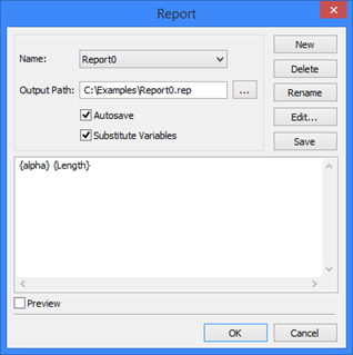
A created template can be written to the report file right from the command dialog, by clicking [Save]. The following text will be written for the example shown on the figure:
Parameters of the machined part for conductor:
Part length: 90
Part height: 50
Number of holes: 1
Hole diameter: 7
Surface slope angle: 10
Chamfer length: 5
Example of Using Report for Unfolding the Clipped Cylinder
As a simple example of using the report mechanism together with the command "AN: Animate Model", consider the solution to the task of constructing a clipped cylinder unfolding.
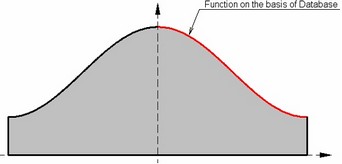
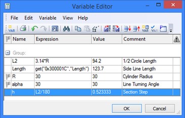
To create the unfolding, a line tilted with respect to the vertical is created at the cylinder's end face. The line parameter (angle) is defined by the variable "alpha". A horizontal line is constructed through the intersection point of the former line and the circle. A segment is constructed along the intersection line of the horizontal line and the side outline edge of the cylinder. Its length is read into the variable "Length" by means of the function "get".
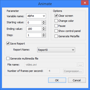
Additionally, a report template was defined in the document for saving the values of the variables "alpha" and "Length". After that, the entire drawing was animated by varying the value of the variable "alpha". In the course of the animation, the variable values were output to the report.
Based on the generated report, a database was created in Excel, which was later used for creating a function in T-FLEX CAD defining the unfolding contour.
Report (the file "Report0.rep") 0 81 1 80.9957 2 80.9826 3 80.9609 … 179 24.0043 180 24 |
|
Profiles
When a part being designed is intended for further processing, which might involve use of CNC centers and creation of numerical control procedures, or for certain other purposes, then the information about the part profile geometry can be saved to a file.
A profile is defined in the commands that create and edit hatches. To designate a hatch as a profile, you would need to set the parameter "Profile" in the hatch properties dialog. If, at the same time, there is no need to fill inside of the profile contour with hatching, then you can designate it as an invisible hatch by selecting the filling method "Invisible".

Profile parameters are output to a file by the command "PR: Write Profile":
Icon |
Ribbon |
|---|---|
|
Tools → Special Data → Profile |
Keyboard |
Textual Menu |
<REP> |
Tools > Special Data > Profile |
After calling the command, select the hatch profile by clicking ![]() . If the drawing contains a single profile, then it will be selected automatically upon calling the command. The command parameters dialog window appears after selecting the profile.
. If the drawing contains a single profile, then it will be selected automatically upon calling the command. The command parameters dialog window appears after selecting the profile.
In this dialog window, first of all you need to select which profile parameters are to write to file:
Properties. This saves information about the profile in one of the selected formats (AutoCAD DXF, AutoCAD DWG, Dragon, EIA);
Geometry. This outputs on the screen or to a file the profile geometrical characteristics (area, perimeter, moments of inertia, etc.).
The "Output Path:" parameter defines the name and the path to the file, in which the profile information will be saved. The file extension will be set automatically, based on the selected parameters and output format. To browse for the file, you can use the button ![]() .
.
If the general profile properties are selected, then the parameter "Output format" allows selecting the desired file format from the list:

AutoCAD DXF (*.dxf). The profile information will be written in the DXF format of AutoCAD system.
AutoCAD DWG (*.dwg). The profile information will be written in the DWG format of AutoCAD system.
DRAGON (*.drg). The profile information will be written in the DRAGON system format.
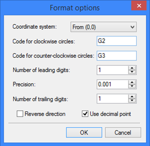
EIA (*.eia). For this format, you can specify the format options by clicking the button [Options…]. The EIA format parameters dialog window will appear on the screen:
Coordinate system. Defines the point, with respect to which the profile coordinates will be counted. You can select from the list: "From (0,0)", "From contour beginning", "Incremental". Code for clockwise circles. Sets the code for identifying arcs defined as clockwise.
Code for counter-clockwise circles. Sets the code for identifying arcs defined as counter-clockwise.
Number of leading digits. Sets the mandatory number of digits before the decimal point when writing numbers to a file.
Precision. Sets the rounding precision for writing numbers to a file.
Number of trailing digits. Sets the mandatory number of digits after the decimal point.
Reverse direction. This lets you get coordinates of the profile in the direction opposite to the specified one.
Use decimal point. This parameter is required for defining a fixed format without the decimal point.
Upon clicking [OK], the profile information will written to the file in the selected format.
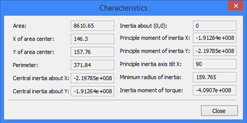
Upon selecting "Geometry" option, the "Geometry" group of parameters becomes accessible. Then, you need to select the necessary geometrical characteristics of the profile: General characteristics or Moment about axis. Upon clicking [OK], the selected characteristics will be displayed in the dialog window. Additionally, if the "Write to file" flag is set, the characteristics will also be saved in an external file "*.pro", defined by the parameter "Output Path".
General characteristics include the following profile properties:
Area and perimeter of the profile;
X and Y of area center of the profile;
Central inertia about X and Y;
Inertia about (0,0);
Principal moment of inertia X and Y;
Principal inertia axis tilt X - the tilt of the principal axis of inertia with respect to the X axis;
Minimum radius of inertia;
Inertia moment of torque.
When selecting a moment of inertia about an axis for examination, after clicking [OK] in the command's parameters dialog, you need to additionally specify the straight line, about which the moment will be calculated. At that time, the following option will be available in the automenu:
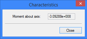
![]() <L> Select Line
<L> Select Line
After selecting the axis, the dialog window will display the calculated moment.