Typing of Routings


Typing of Routings |
|
In order to automate routings design process, objects can be associated with certain types. Types allow you to exclude mistakes in operations of connecting routing elements to each other.
For description of objects compatibility rules and assignment of types use command TI: Connection Types. There, you can assign a valid correspondence between the routes and fittings, between the different types of routes.
It is possible to create objects with basic typing. The basic types include Wiring, Ventilation, Pipeline.
For these basic types menu Routing has commands to create connection points, routes, harnesses, routing objects, as well as command for filling route with style.
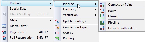
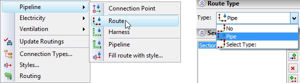
When you call command Route from one of the three groups of Routing text menu, system opens dialog of route command with the corresponding value of Type parameter (Wiring, Ventilation and Pipeline). To clarify type use option Select type in the drop-down menu. It will offer you types, which are the children of the base type.
If Route command is called using text menu Construct >> Route, by using "Select type" option you can select type from all types available in the library.
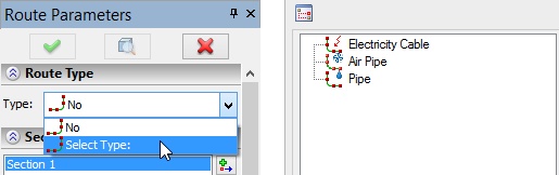
In the drop-down list displays the 10 most recently used types. When you call one of the commands with the base typing you will get types derived only from this base type. When you use the general Route command you will get all used types.
To adjust compatibility of different types you can use Editor of Connection Types.
Editor of Connection Types
With the help of editor of connection types you can set compatibility rules for various types of routings. Compatibility rules help to avoid mistakes when working with various libraries and routings within the same project. For example, avoid accidental connection of low-voltage and high-voltage cables in the design process.
Editor can be called using Connection Types command of the Routing text menu.
Keyboard |
Textual Menu |
Icon |
|---|---|---|
<TI> |
Tools >> Routing >> Connection Types … |
|
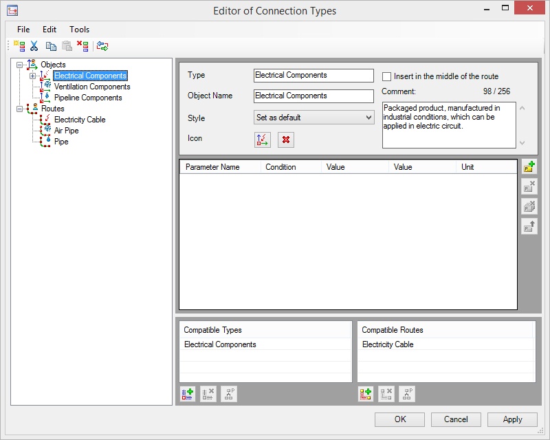
In the left pane there is a tree of types. It consists of two main parts: "Objects" and "Routes".
Above the tree of types there is a toolbar for its editing.
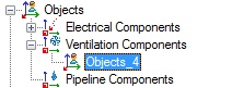
![]() Create. Allows you to create a new type. Object will be added to the selected type from the list. Parameters of a new type are described below.
Create. Allows you to create a new type. Object will be added to the selected type from the list. Parameters of a new type are described below.
![]() Cut. The selected object will be cut from tree.
Cut. The selected object will be cut from tree.
![]() Copy. Allows to copy type
Copy. Allows to copy type
![]() Paste. Allows to insert type. Works with with options Cut and Copy.
Paste. Allows to insert type. Works with with options Cut and Copy.
![]() Delete. Allows to delete selected type.
Delete. Allows to delete selected type.
![]() Editor of Physical Parameters. Provides access to the internal directory of the physical parameters. Work with the directory is described below.
Editor of Physical Parameters. Provides access to the internal directory of the physical parameters. Work with the directory is described below.
Parameters of type
The right pane displays the set of parameters of the selected type.
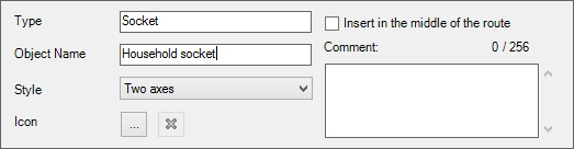
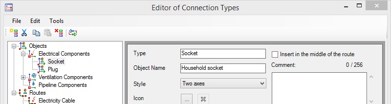
Type. In this field you can specify unique name of the type to which the object belongs. Type name will appear in the list on the left side of the Editor of Connection Types and the drop-down list of types when you create objects (connection points and routes).
Object Name. Specifies the name of objects for a given type. This name will be displayed in the model tree. Names can be the same for different objects.
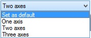
Style. Specifies the number of axes required for the proper connection of objects.
|
For example, such connection as "plug - socket" requires two axes to match. Style is taken into account when creating connection points and routes. |
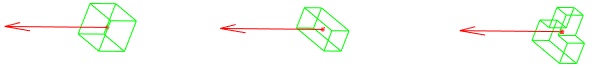
One axis |
Two axes |
Three axes |
Icon. It allows you to set icon to be displayed to the left of the type. For selecting icon for the file you can use the button![]() . In the window that appears you can see the available standard icons. To remove element icon, use the button
. In the window that appears you can see the available standard icons. To remove element icon, use the button ![]() .
.
![]()
Comment. In this field you can enter a comment to the selected element. The number of characters available for comment is displayed above the field.
For each element you can set a group of parameters.
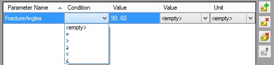
Parameter Name. If two objects of the same type of parameter names coincide, these parameters are compared. When incompatibility is found, you cannot connect the objects.
Condition. Condition can be selected from the drop-down list.
Value. Is taken into account when comparing parameters.
Physical Parameter. From the drop-down list you can select the physical parameter. Physical parameters are set in the Editor of Physical Parameters.
For more information about editor of physical parameters refer to section "Physical Parameters" below.
Unit. After selecting the physical parameter you can use set the corresponding unit.
On the right side of the dialog there is a set of buttons to control the inheritance of parameters. By default, objects inherit all parameters of the upper level objects.
Button ![]() shows parameters that selected type inherits. To change the inherited parameters use option
shows parameters that selected type inherits. To change the inherited parameters use option ![]() .
.
![]()
![]()
![]() - options allow you to add or delete parameters from the list.
- options allow you to add or delete parameters from the list.
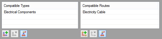
Compatible types can be set in the bottom of the window.
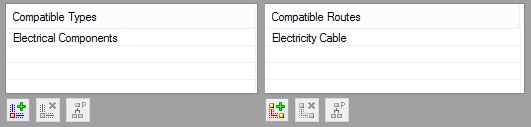
Options ![]() and
and ![]() allow you to add compatible types and routes from the list. Options
allow you to add compatible types and routes from the list. Options ![]() and
and ![]() allow you to delete previously added types and routes.
allow you to delete previously added types and routes.
Option ![]() allows you to control inheritance of parameter types. When enabled, all objects within a type inherit all of its compatible elements. After disabling the option, you can delete all but one inherited compatibility.
allows you to control inheritance of parameter types. When enabled, all objects within a type inherit all of its compatible elements. After disabling the option, you can delete all but one inherited compatibility.
Only compatible types can be set for the routes.
The tree structure and description of types is contained in ConnectorType.xml file. To manage this file from the "File" menu, use the following commands:
- Save (active, if any item in the tree has been changed): saves ConnectorType.xml file in “C:\Users\User_name\AppData\Local\ Top Systems\ T-FLEX CAD 3D…” folder.
- Import: replaces the contents of the current ConnectorType.xml file with the contents of the imported file. If ConnectorType.xml file has been modified before importing, system would prompt to save it under another name.
When importing tree of types there are two options:
- With replacement: current list will be completely replaced by the list from external file.
- With addition of: the user will be prompted to select the types that need to be put in the current list. The import list will be filtered not displaying the types that already exist in the current list.
- Export: saves ConnectorType.xml file to the specified location. If desired, you can specify a different name for the file.
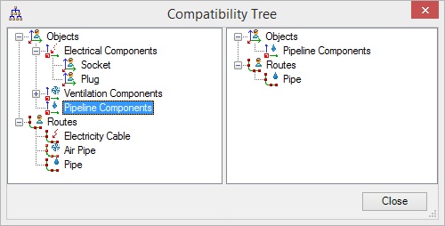
Compatibility Tree
Command “Tools/Compatibility Tree” of the “Editor of Connection Types” displays compatibility rules in a separate window. For the element selected in the left part of window systems shows on the right side all compatible objects and routes. Tree allows to see the current structure of compatibility.
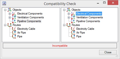
Compatibility Check
Command “Tools/Compatibility Check” of the “Editor of Connection Types” allows you to check compatibility of any pair of elements in the list of objects and routes. Select item in the left pane and item in the right pane. Message in the bottom will tell about the presence or absence of compatibility.
Physical Parameters
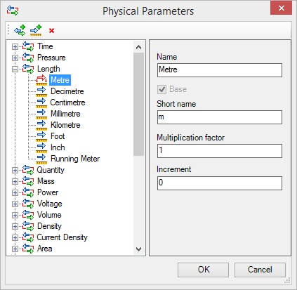
Command “Edit\Editor of Physical Parameters” of the “Editor of Connection Types” ![]() displays the internal directory of physical parameters for the editor of connection types. For each parameter there is a list of units with the name and the short name.
displays the internal directory of physical parameters for the editor of connection types. For each parameter there is a list of units with the name and the short name.
Flag Base sets the default measurement unit. For other units of measure there is Multiplication factor for conversion to the base unit. List of parameters and units of measurement can be edited using the following commands:
![]() - Add parameter
- Add parameter
![]() - Add unit
- Add unit
![]() - Delete
- Delete