Fittings


Fittings |
|
Fitting is a connecting part of pipeline, which is usually located at branching places, turns and transitions to another diameter. Fittings are used for sealed overlap of the pipeline and other auxiliary purposes.
It is convenient to use smart-fragments as fittings. Smart-fragments adapt to objects already existing in the model and affect geometry of connected fragments.
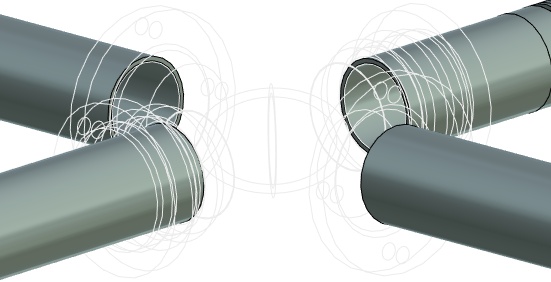
For example, when you insert a cross fitting between two pipes, the crossing pipes will be automatically divided each into two parts. Their ends will be automatically transformed according to the requested connection type.
Special variables, connectors, LCS and macro provide an automatic link with parameters of other routing elements. The macro is included into the fitting document file.
When you need a new fitting you have to create a 3D model file with a special macros that will be used as a 3D fragment. Creation and usage of each fitting type is described below.
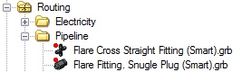
Ready to use library fittings files include “Smart” suffix in their names. You can enlarge set of such elements if it is necessary.
Fitting gets part of external variables values from the pipeline parameters. For example fitting can get the pipe diameter. Fitting can also pass parameters values to the pipe, if it is set in the fitting file.
There are following fittings types defined by default: Cap, CornerFracture, CornerRadius, Tee, Crossing, Adapter, Clamp, CornerEnd, Inset.
Fitting Insertion
It is easy to use drag’n’drop mechanism for fitting insertion.
Options for defining fitting location appears right after drag’n’drop of the fitting.
|
<P> |
Select path |
|
<T> |
Select pipe |
When option ![]() is selected, the fragment is placed on the selected path point. When you select
is selected, the fragment is placed on the selected path point. When you select ![]() , system defines appropriate point for fixing on the selected pipe (for example, crossing), if necessary.
, system defines appropriate point for fixing on the selected pipe (for example, crossing), if necessary.
There is a different set of options for each fitting type. It appears after path or pipe selection.
|
<R> |
Rotate fragment along main axis |
|
<T> |
Rotate fragment along alternative axis |
|
<V> |
Select next fixing point |
Options ![]() and
and ![]() allow to rotate the fragment around main and alternative directions, changing location of trunks and branches.
allow to rotate the fragment around main and alternative directions, changing location of trunks and branches.
Option ![]() is available if the fragment is located on the crossing of two pipes/paths.
is available if the fragment is located on the crossing of two pipes/paths.
If the fragment (tee or crossing) is located at the crossing point of paths, you can’t rotate or translate it using manipulator.
For CornerFracture, CornerRadius, CornerEnd:
|
<R> |
Rotate fragment |
|
<F> |
Select next fixing point |
The next suitable fixing point for fitting will be automatically found after pressing of ![]() or
or ![]() options. The points will be cyclically searched upon further continuous option usage.
options. The points will be cyclically searched upon further continuous option usage.
The corner can be located on trunks and endings of the pipe.
For Inset, Clamp:
|
<D> |
Select pipe for Y direction |
|
<R> |
Rotate fragment |
When the option ![]() is active you need to select pipe, related to which the Y direction will be defined.
is active you need to select pipe, related to which the Y direction will be defined.
For Cap, Adapter:
|
<R> |
Rotate fragment |
This type of fittings limits pipe on endings.
For all inserted smart-fragments the following options are available:
|
<E> |
Wireframe |
|
<N> |
Insert new fragment after confirmation |
Wireframe. Allows to switch between wireframe mode and rendering mode of the model.
Wireframe mode |
Rendering mode |
Insert new fragment after confirmation. A new fragment similar to the inserted one will be added after confirmation button pressing.
Fittings Basic Highlights
When you insert a fitting at the beginning or end of the pipe, the pipe is not divided. When you change fixing type the pipe will be divided into two parts if possible. The original parameters of pipe endings will be restored.
After the fitting insertion or replacement system determines necessity of the pipe dividing. Unused pipe part will be suppressed and removed after exiting the command.
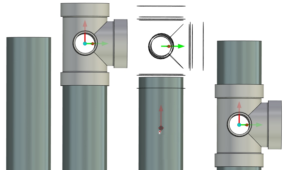
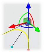
Special manipulator is used to define fitting position. It allows to move fitting and rotate it around the axis.

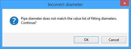
If fitting does not match the pipe, the corresponding message will appear.
Special window Action appears when you edit a fitting. Here you can select option for editing the current fitting, selecting a new fitting to replace the current or cancel editing.
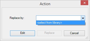
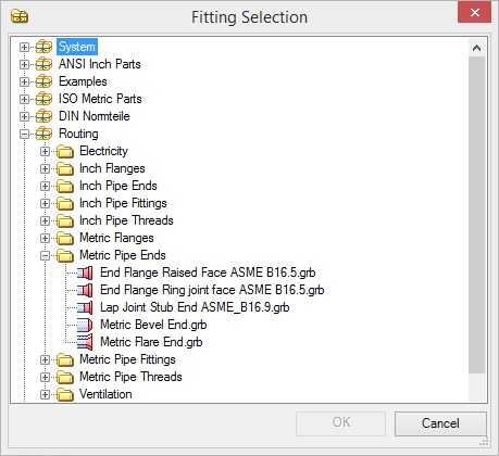
To replace a fitting choose option <Select from library> and select necessary library fragment in Fitting Selection window. After selection, you need to press [Replace] button.
After fitting selection the system exit from edition command automatically.
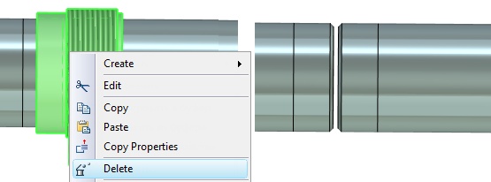
When you delete a fitting, linked pipes won’t be deleted.
Fittings Parameters Names
Table of external key variables of smart-fragment.
Variable name |
Usage |
Description |
DiameterIn1 |
Manages input diameter of main direction fitting |
Is necessary for Cap, CornerXxx, Tee, Crossing, Adapter, Clamp |
DiametrOut1 |
Manages output diameter of main direction fitting |
Is necessary for CornerXxx, Tee, Crossing, Adapter |
DiametrIn2 |
Manages input diameter of alternative direction fitting |
Is necessary for Crossing |
DiametrOut2 |
Manages output diameter of alternative direction fitting |
Is necessary for Tee, Crossing |
External variable Diameter *** is responsible for link between the respective diameters of fitting and pipe. Due to the variables, macro can get diameter of pipe to which fitting is attached and set the appropriate diameter of fitting.
When creating a smart fragment it is possible to use from one (lug, cross with identical diameters of all branches) to four (cross with four different diameters) external variables, depending on the number of input and output fitting diameters.
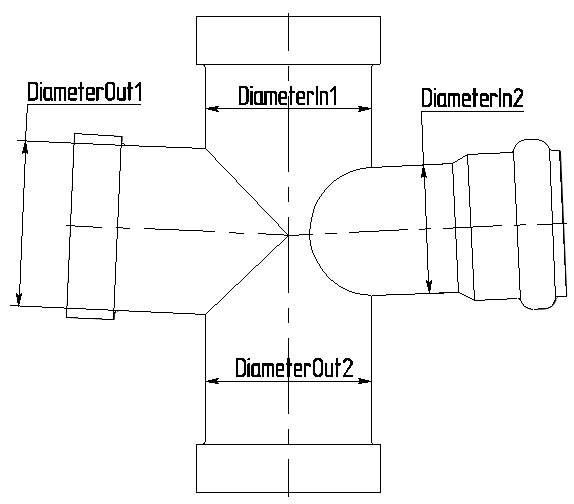
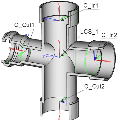
Table of smart-fragment key LCS.
Object |
Description |
LCS_1 |
The fragment source LCS must be set as LCS by default in the fragment document parameters. |
C_In1, C_Out1, C_In2, C_Out2 |
Connectors names of input/output main and alternative directions |
LCSs listed in the table are responsible for cutting pipe for which fitting is inserted.
LCS_1 responsible for position of fitting on the pipe is the main LCS that must be created for joining fitting with the fragment. The remaining four LCSs are responsible for joining pipes of appropriate diameter and the emergence of the connecting elements (flange and thread) at coupling place of pipe with fitting. These LCSs are considered in macro.
Table of key connector parameters that define smart-fragment insertion logic:
Parameter name |
Usage |
Description |
autoFilePipeEnd |
Pipe ending/beginning if connector is located on pipe end. Can be omitted. |
Template of the parameter value: <library>file_name.grb Parameter functions: - creates cosmetic thread on the pipe - cuts the edge for weld - creates flaring |
autoLength |
The fragments name in the connector direction |
Sum of input and output connector lengths is equal to the length of the direction (main or alternative) |
autoDiameter |
Pipe diameter will be taken from fitting |
If missed the original pipe diameter is used. |
autoThickness |
Pipe thickness will be taken from fitting |
If missed the original pipe thickness is used. |
Auto – manages the command operating logic when the smart-fragment with this connector is inserted.
The above parameters allow you to specify additional options when you insert the fitting.
Fittings Smart-fragments Behavior in Pipe Systems
Variants of interaction with other fittings
1. |
Y-shaped bend |
●Creates inner cosmetic thread on pipe ●Creates outer cosmetic thread on pipe ●Divides pipe segment into two segments ●Divides pipeline into more than two segments ●Modifies pipe diameter from larger to smaller and back ●Cuts edge for weld ●Inserted in the middle of pipe segment ●Inserted on pipe ends ●Inserted on pipe rounds ●Inserted on pipe corners ●Interaction with a single pipe ●Interacts several pipes ●Interacts other fittings ●Interacts intersecting branches of pipeline |
2. |
Adapter |
●Creates inner cosmetic thread on pipe ●Creates outer cosmetic thread on pipe ●Divides pipe segment into two segments ●Modifies pipe diameter from larger to smaller and back ●Inserted on pipe ends ●Inserted in the middle of pipe segment ●Interaction with a single pipe ●Interacts several pipes ●Interacts other fittings ●Interacts with parallel branches of pipeline ●Makes the flaring of pipe/tube/hose |
3. |
Branch
|
●Creates a hole in pipe ●Cuts edge for weld ●Inserted in the middle of pipe segment ●Interaction with a single pipe ●Interacts with several pipes ●Interacts intersecting branches of pipeline |
4. |
Bushing |
●Creates inner thread on pipe ●Creates outer cosmetic thread on pipe ●Divides pipe segment into two segments ●Modifies pipe diameter from larger to smaller and back ●Cuts edge for weld ●Inserted on pipe ends ●Inserted in the middle of pipe segment |
5. |
Lock nut |
●Creates outer cosmetic thread on pipe ●Inserted in the middle of pipe segment ●Interaction with a single pipe |
6. |
Set-off pipe bend |
●Creates inner thread on pipe ●Creates outer cosmetic thread on pipe ●Cuts edge for weld ●Inserted on pipe ends ●Cuts second part of pipe ●Modifies pipe diameter from larger to smaller and back ●Cuts edge for weld ●Inserted in the middle of pipe segment ●Interaction with a single pipe ●Interacts with several pipes ●Interacts with parallel branches of pipeline ●Interacts other fittings |
7. |
Valve |
●Creates inner thread on pipe ●Creates outer cosmetic thread on pipe ●Divides pipe segment into two segments ●Cuts second part of pipe ●Modifies pipe diameter from larger to smaller and back ●Cuts edge for weld ●Inserted on pipe ends ●Inserted in the middle of pipe segment ●Interaction with a single pipe ●Interacts with several pipes ●Interacts other fittings ●Interacts intersecting branches of pipeline |
8. |
Bend |
●Creates inner thread on pipe ●Creates outer cosmetic thread on pipe ●Divides pipe segment into two segments ●Cuts second part of pipe ●Modifies pipe diameter from larger to smaller and back ●Cuts edge for weld ●Inserted on pipe rounds ●Inserted on pipe corners ●Inserted in the middle of pipe segment ●Interaction with a single pipe ●Interacts with several pipes ●Interacts other fittings ●Interacts intersecting branches of pipeline |
9. |
Crossing |
●Creates inner thread on pipe ●Creates outer cosmetic thread on pipe ●Divides pipe segment into two segments ●Cuts second part of pipe ●Modifies pipe diameter from larger to smaller and back ●Cuts edge for weld ●Inserted on pipe ends ●Inserted in the middle of pipe segment ●Interaction with a single pipe ●Interacts with several pipes ●Interacts other fittings ●Interacts intersecting branches of pipeline |
10. |
Coupling |
●Creates inner thread on pipe ●Creates outer cosmetic thread on pipe ●Divides pipe segment into two segments ●Modifies pipe diameter from larger to smaller and back ●Inserted on pipe ends ●Inserted in the middle of pipe segment ●Interaction with a single pipe ●Interacts with several pipes ●Interacts other fittings |
11. |
Cap |
●Creates inner thread on pipe ●Creates outer cosmetic thread on pipe ●Cuts second part of pipe ●Inserted on pipe ends ●Interaction with a single pipe ●Interacts other fittings |
12. |
Pipe clamp |
●Changes geometry of the 3D path ●Interacts with several pipes ●Interacts intersecting branches of pipeline ●Interacts with parallel branches of pipeline ●Interacts intersecting branches of pipeline |
13. |
Reducer |
●Creates inner thread on pipe ●Creates outer cosmetic thread on pipe ●Divides pipe segment into two segments ●Modifies pipe diameter from larger to smaller and back ●Cuts edge for weld ●Inserted on pipe ends ●Inserted in the middle of pipe segment ●Interaction with a single pipe ●Interacts with several pipes |
14. |
Tee
|
●Creates inner thread on pipe ●Creates outer cosmetic thread on pipe ●Divides pipe segment into two segments ●Cuts second part of pipe ●Modifies pipe diameter from larger to smaller and back ●Cuts edge for weld ●Inserted on pipe ends ●Inserted on pipe rounds ●Inserted on pipe corners ●Inserted in the middle of pipe segment ●Interaction with a single pipe ●Interacts with several pipes ●Interacts other fittings ●Interacts intersecting branches of pipeline |
15. |
Seal |
●Interacts other fittings |
16. |
Flange |
●Divides pipe segment into two segments ●Inserted on pipe ends ●Inserted in the middle of pipe segment ●Interaction with a single pipe ●Interacts other fittings |
17. |
Pipe housing |
●Inserted in the middle of pipe segment ●Interaction with a single pipe ●Inserted on pipe rounds ●Inserted on pipe corners ●Interacts with several pipes ●Interacts with parallel branches of pipeline ●Interacts other fittings |
18 |
Compensator |
●Divides pipe segment into two sections ●Cuts edge for weld ●Interaction with a single pipe ●Inserted on pipe ends ●Inserted in the middle of pipe section ●Interacts other fittings |
Macros Creation
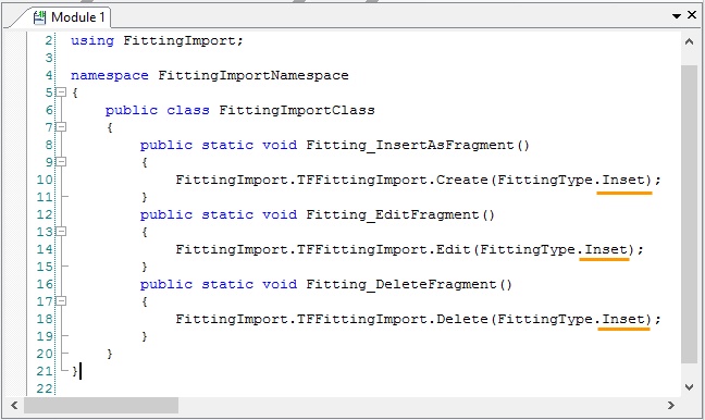
When you create a new fitting a standard macro text is added into its file. One of the fittings types that were listed above is specified in the macro.
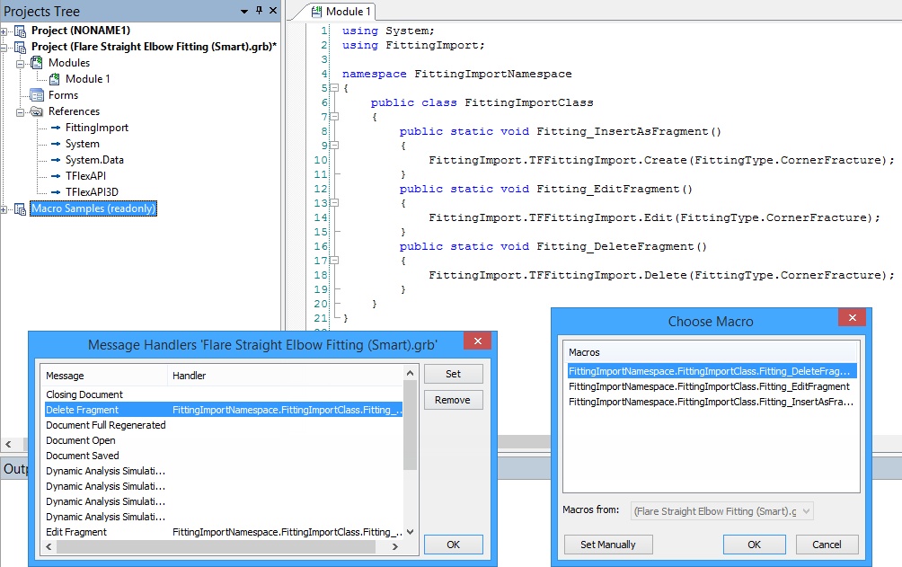
Here is example of typical macro text for the “Crossing” type.
using System;
using FittingImport;
namespace FittingImportNamespace
{
public class FittingImportClass
{
public static void Fitting_InsertAsFragment()
{
FittingImport.TFFittingImport.Create(FittingType.Crossing);
}
public static void Fitting_EditFragment()
{
FittingImport.TFFittingImport.Edit(FittingType.Crossing);
}
public static void Fitting_DeleteFragment()
{
FittingImport.TFFittingImport.Delete(FittingType.Crossing);
}
}
}
More information about macro can be found in “Macros” chapter.
Also you need to set three message handlers “Fitting_InsertAsFragment”, “Fitting_EditFragment”, “Fitting_DeleteFragment”.
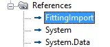
To compile the macro you need to add link to the FittingImport in the project.
Smart-fragment Creation Example
General steps for successful creation of a smart-fragment are listed in this example.
For convenience, the smart-fragment creation is divided into four stages:
●Body for fitting creation
●Body for creation of the cutout shape in pipe
●Fitting parameters managing
●Macro creation
There are special rules for LCS, connectors and variables when you create a fitting. Names of variables and LCSs and their description are listed in “Fittings parameters names” section.
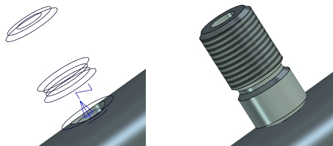
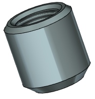
Fitting Body Creation
To begin with, you need to create a fragment body. The 3RO:Rotation and 3AT:Thread were used to create the boss.
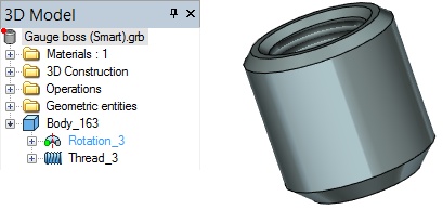
More information about the rotation and thread operation can be found in “Rotation” and “Thread” chapters.
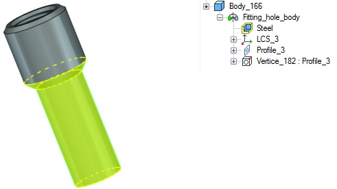
Fitting Hole Body Creation
The next step is creation of a fitting hole body.
Body for defining an insert in pipe is a fitting element that defines the form and shape of a hole in pipe, in which the fitting is inserted. After insertion, this body disappears.
You need to specify input diameter of main direction fitting “DiameterIn1” and main LCS “LCS_1” for the boss creation.
More information about variables names can be found in “Fitting parameters names” section.
Setting Diameter Variable
The diameter is specified in the variables editor. The variable defines diameter of pipe in which the fitting is inserted and specifies fitting location.
![]()
You can set any value for diameter variable. The macro automatically identifies pipe diameter and add its value to the variables, when the fitting is inserted into an assembly.
You need to set External variable flag for the variable.
LCS Creation
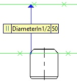
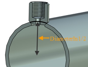
Construction line was created in the example to specify LCS location. The line is at distance “DiameterIn1/2” from the face of the boss cylindrical part. The pipe diameter is half divided that’s why the boss will be located on the pipe.
|
|
Line that defines LCS location |
Boss location on the pipe |
The LCS is renamed to LCS_1. The name was taken from the “Key smart-fragments objects” table.
There is no need to create connectors (C_In, C_Out) because there are no fitting elements to connect with the boss.
In this case, the fitting will not join any piping elements or other fittings, so the creation of additional connectors (C_In, C_Out), diameters (DiameterIn2, DiameterOut), or their parameters are not required.
Body Creation
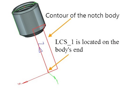
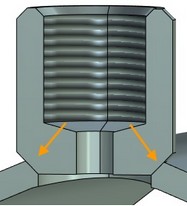
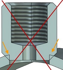
The next step is to create a body to define shape of the cutout in pipe. Contour of the body should follow the shape of the cutout in pipe, so that when you insert fitting there is no intersection of the fitting and the pipe.
|
Without intersection
With intersection |
Length of body should depend on LCS_1 position. This is done in order to be able to adjust the position of the fitting on the pipe depending on the pipe diameter.
It is better to have the body with the most simple geometry - a box or cylinder. This will reduce the time of the pipeline regeneration.
If the body is not created, a cutout will have the form of the inserted fragment.
In this case, the body is obtained by rotating profile around axis.
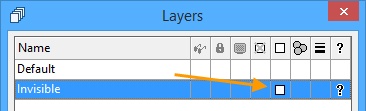
Body to set the shape of cutout in the pipe should be hidden in the 3D scene and on the drawing. In order to hide it you need to do the following.
In the editor of layers, create a new layer and name it - "Invisible" and put mark in the Visible only when inserted in assembly.
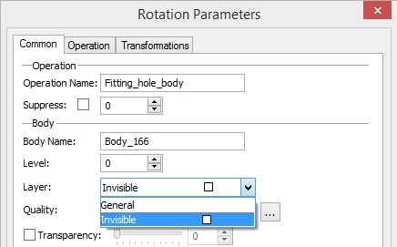
In the parameters of created body on the General tab, you must specify the previously created layer "Invisible", then the body will be hidden in the 3D scene
Adjusting Fitting Parameters
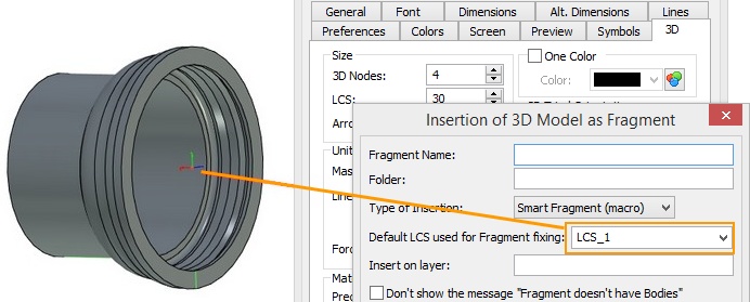
After creating the fitting body it is necessary to set the parameters for its insertion into assembly as a smart fragment. To do this, use ST: Set Document Parameters command, go to 3D Fragment tab.
In the window that appears you must:
Set Type of Fragment Insertion – Smart Fragment (macro). System will use macro created in Macro Editor when inserting this body.
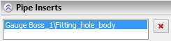
Set flagIn the Automatically create Boolean operation section. From the drop-down list, you must should select operation type Subtraction from the drop-down list - subtraction, so that the body create a cutout in the pipe, and in the drop-down list Create operation with select the name of the body that will be used for Boolean operations. In this case - "Fitting_hole_body".
Setting the above parameters allows system to automatically execute macro to create Boolean operation when you insert the smart fragment.
After performing Boolean operation body used as a cutout in the pipe disappears. It will be referenced in the section Pipe Inserts in the Properties window for the selected element of the pipeline.
Macro Creation
The following is the sequence of actions to create a macro for inserting a smart fragment:
Use macro editor to create a new macro. Macro text for various fittings differs only in the type indicated in parentheses. In this case, this is type "Inset".
The you need to define three message (event) handlers:
●Inserting as a fragment (Fitting_InsertAsFragment),
●Editing (Fitting_EditFragment),
●Deleting (Fitting_DeleteFragment).
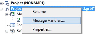
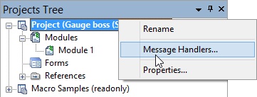
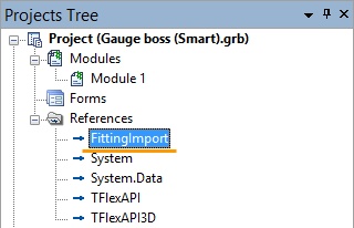
To set the handler you must select the project and from the context menu choose Message Handlers ....
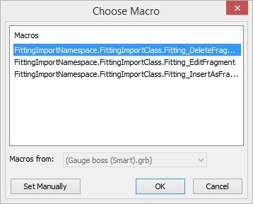
In the window that appears choose one after another three lines "Delete Fragment", Edit Fragment, "Insert as a Fragment" and select them using the macro button [Set].
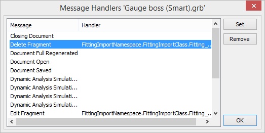
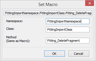
Since the main macro has been previously created in the macro editor, the list will appear from which you can select the desired part of the macro. Macro can be set manually, if necessary, by pressing [Set Manually].
In order to successfully compile the macro add link to FittingImport in the project.
After completing all the above items, the fragment file must be saved. Now the created fitting can be used for insertion into assembly using Drag’n’Drop method.
More information about creating macros can be found in the "Macros" chapter.
Example of creating pipe endings and connections
When you create models for pipe middles and endings you should considered a set of rules.
To add new models for pipe middles and endings into the library use command:
|
<С> |
Library Configuration |
More information about configurations can be found in “Holes” chapter.
In the fragment file you must create the following variables:
●Diameter or D - pipe diameter (permissible values range from 0 to 10000)
●Thickness or T - pipe wall thickness (permissible values range from 0 to 10000)-
●InnerDiameter or InnerD – flag for usage of internal diameter (possible values 0 or 1)
Note. Variable InnerDiameter (D) can be used for the suppression of one of the bodies in the fragment file. One body will be visible when using internal diameter, the second - using external.
Guidelines for creating fragment of ending and connection
After creating 3D model, you need to:
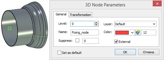
Create external 3D node (there must be only one). This node will limit the adjoining pipe. It should be placed on the "inner end" of fragment body.
Create external LCS. This LCS should be placed on the "outer end" of fragment body. It will be used for fixing the fragment. It must be assigned as a primary fixing LCS in the document properties command on the 3D tab, button [Fragment].
More information on how to create LCS can be found in the chapter "Local Coordinate Systems".
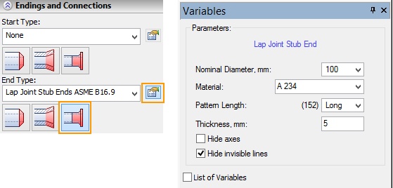
Create custom dialog for entering values of external variables (optional step). This dialog is automatically embedded in the Properties window when you call editing of ending variables in the command of pipeline creation/editing.
Learn how to create a dialog in the chapter "Controls. Creation of Custom Dialogs."
Create icon with the command Tools >> Special Data >> Icon. (Optional step).
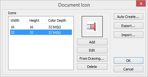
Learn how to create icons in chapter "Document Preview and Icons"
In the variable editor add diagnostics for invalid combinations of variable values.
Read more about diagnostics functions in chapter “Variables”.
Guidelines for creating fragment of the middle part of pipe
When you need to create some specific pipe geometry like corrugated pipe you may use special mechanism for defining pipe “middle” using fragment.
In the fragment file you must create variables described in the beginning of this section: Diameter, Thickness, InnerDiameter.
To create a 3D model of the middle of the pipe, you can use any convenient operation, such as sweeping along a path. It is important that the body is based on a 3D path.
After creating 3D model, you must set parameters in Adaptive Fragment command. This will create a pipeline using any selected route.
Read more about how to create adaptive fragments in chapter "Adaptive 3D Fragments."
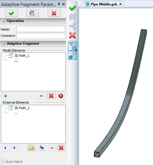
Name. Parameter specifies the name of operation, which will be assigned to the pipe using this fragment.
Geometrical parameters:
- Path (3D path or route). Element that defines the path of the pipeline.
- 3D pipe start node
- 3D pipe end node
It is important to comply with sequence of geometrical parameters in the list. The first must be path, and then the start and end points.
Creation of icons and dialog of external variables for the fragment is not a mandatory action.
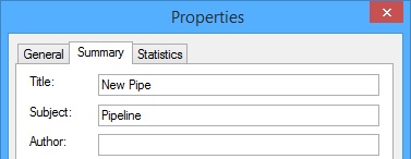
Name that appears in the list of endings and connections in the command of pipeline creation can be set in command File >> Properties >> Summary.
After performing all the above steps, you must save the file.