Thread


Thread |
|
T-FLEX CAD supports creation of cosmetic threads on cylindrical and conic faces of a three-dimensional model. A cosmetics thread is not the exact geometrical representation of an actual thread that can be created in the command "3SR: Create Spiral". Nevertheless, it is quite suitable for most of the tasks arising in thread modeling, while consuming much less computational resources.
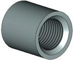
A cosmetic thread is a texture applied to the selected face. The simulated image reflects the pitch, direction and boundaries of the thread.
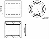
When creating drawings by projecting cosmetic threads, the standard thread notation is automatically generated on the projections.
Main concepts. Operation capabilities
Cosmetic threads are created based on a special database "Threads.mdb", located in the folder …\Program. The database contains geometrical parameters of standardized threads according to the engineering standards. If necessary, the database can be appended with custom threads. You can also create nonstandard threads directly in T-FLEX CAD, without using the database.
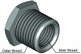
When creating a cosmetic thread, you need to select the base face (cylindrical or conic), define the thread type (standard) and side (outer or inner) and the main parameters. To define the thread parameters, use either the property window or the standard parameters dialog box. All of the thread parameter values can be defined using variables. Additionally, you can specify the thread offsets from the ends of the base face or from an arbitrary 3D object. The position of the thread end can also be defined relative to its start, by actually specifying the thread length.
The parameters of the standard thread – the pitch, the working profile height and the class – can either be set by the system automatically or manually defined by the user.
In the Autoadjust mode, the system sets the thread parameters from the database, based on the diameter of the base face. When the base diameter is modified, the thread parameters are adjusted automatically.
In the manual mode, the user defines the thread parameters by numerical values or by using variables. The entered values are checked against those in the thread database. If the input diameter or pitch is not defined for the respective thread type, the value will be taken from the database nearest to the specified one. In this case, the thread parameters will not adjust to the base face diameter modifications. When creating a nonstandard thread (not existing in the thread database), all its parameters are defined manually.
The combination of parameters and the thread behavior depends on its property – being an outer or an inner thread. For an outer thread, the base face diameter is considered the outer diameter, while for an inner thread it is the inner diameter. For the same base face diameter, the system-defined parameters will be different for outer and inner threads. The thread side (outer or inner) is a characteristic constant and can be defined in two ways.
In the first way, the thread side is defined automatically at creation. Inner threads are created on concave faces, while outer ones – on the convex faces. If the face later changes from convex to concave or vice versa due to Boolean operations or other body modifications, the thread will disappear. The automatically defined thread side is suitable for most of threads. In the second way, the thread side is explicitly defined by the user at creation, regardless of the current geometry of the base face. This may be necessary, for example,when creating fragments of holes.
In the fragments, the thread is applied to the convex face, yet is marked as inner. Upon assembling the fragment, performing a Boolean subtraction makes the base face of the thread concave. Thus, after the Boolean operation the thread is carried over to the resulting inner cylindrical face of the hole.
When creating a 2D projection, the necessary graphic lines are created automatically to mark the thread. The parameters of such graphic lines are defined separate from the rest.
Creating thread
To create a thread, use the command "3AT: Create Thread":
Icon |
Ribbon |
|---|---|
|
3D Model → Modify → Thread |
Keyboard |
Textual Menu |
<3AT> |
Operation > Thread |
First, you need to select a cylindrical or conic face in the 3D window to which the thread will be applied. Upon entering the command, the following automenu option is active:
![]() <F> Select cylindrical face
<F> Select cylindrical face
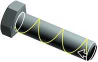
Upon the selection, a schematic image of the thread spiral is displayed on the face, along with the marks for the thread start and end. By default, the thread is applied to the full extent of the selected face. The arrow on the thread image shows the direction of cutting the thread. The cutting direction is defined by the face selection: the thread start is set at the face end nearest to the pointer at the time of clicking ![]() for face selection. It is necessary to know the cutting direction in order to correctly define the boundaries of the thread. Upon selecting the first face, the option
for face selection. It is necessary to know the cutting direction in order to correctly define the boundaries of the thread. Upon selecting the first face, the option ![]() stays active, allowing to select another face of the same type and diameter for extending the thread. This allows creating a thread spanning several faces.
stays active, allowing to select another face of the same type and diameter for extending the thread. This allows creating a thread spanning several faces.
Defining main thread parameters
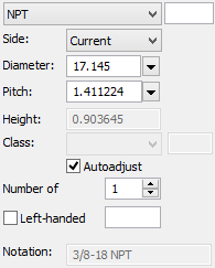
Among thread parameters (in the property window or the parameters dialog box of the option ![]() ), select the thread standard: one of the standards provided in the database, or non-standard. An input box next to the combo box of the thread the standards allows defining the thread standard, using a numerical value or a variable (this number corresponds to the record number of the thread in the database).
), select the thread standard: one of the standards provided in the database, or non-standard. An input box next to the combo box of the thread the standards allows defining the thread standard, using a numerical value or a variable (this number corresponds to the record number of the thread in the database).
The parameter "Side" defines the thread property being outer or inner. One of the three choices can be selected from the combo box: Current. The side of the thread is determined by the type of the base face at the time of the thread creation. If the type of the base face changes to the opposite later in modifications (for example, as a result of a Boolean operation), the thread will be deleted as inappropriate for the face. Outer. The thread is considered outer (regardless of the type of the base face). When using automatic setting of parameters, the face diameter is considered the outer diameter of the thread. Inner. The thread is considered inner (regardless of the type of the base face). When using automatic setting of parameters, the face diameter is considered the inner diameter of the thread. |
|
The preferred setting for most threads is "Current". The choices "Inner" and "Outer" should be used on faces, whose type is expected to flip later. For example, when creating fragments of holes that are subtracted from the base body when assembled, the "Inner" thread is created, even though it is the outer face in the fragment.
When selecting the nonstandard thread type, all its parameters, including the notation on the drawing, are always defined by the user manually by numerical values or by variables.
For standard threads, Autoadjust mode is turned on by default (the flag "Autoadjust"). In this case, the thread parameters are set according to the diameter of the base face. The nearest to the actual diameter value is picked from the set of diameters of the specified thread. Should two satisfactory values be found, the one is picked with the higher priority according to the standard guidelines. Then, the most suitable pitch is picked among the ones corresponding to the chosen diameter (for a metric thread, this will be the large pitch, for other threads – the one recommended by the respective standard).
The Autoadjust mode is not limited to the thread creation. When modifying the diameter of the base face with the Autoadjust mode turned on, the thread parameters will be adjusting automatically as well.
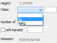
The selected diameter and pitch are displayed in the respective boxes of the parameters dialog ("Diameter", "Pitch"). The box "Height" reflects the height of the thread working profile for the given pitch. If necessary, you can select another pitch from the system-offered list. In this case, when performing automatic adjustment of the face diameter modifications, the nearest to the manually defined pitch will be set, rather than that recommended by the standard.
When the Autoadjust mode turned off, you can specify arbitrary parameter values or variable names for the standard thread parameters in the parameters dialog box. Nevertheless, even in this case, the thread parameters are taken from the database. The values are selected nearest to those input by the user. Such parameters do not change with modifications of the base face diameter.
The additional "Class" field allows defining a tolerance or a precision class for the thread (in some standards). The value of this parameter can be selected from the pull down list, if the respective tolerance or class of precision values were defined in the thread database. The contents of such list are based on the values entered in the database, respective to the thread type and standard.
The field "Number of threads" defines the number of thread sets.
The threads are created right-handed by default. If you need to create a left-handed thread, turn on the flag "Left-handed". The input box on the right of the flag allows controlling its state by using a numerical variable (the value "1" means the flag is on, "0" – off).
The "Notation" field displays the thread notation that will be used on a projection.
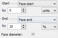
Defining offsets
By default, the thread is applied to the whole extent of the selected face. That means, zero offsets from the face ends are used. If necessary, you can specify a different offset value or modify the way of defining the offsets – with respect to the face ends, relative to an arbitrary 3D object, etc.
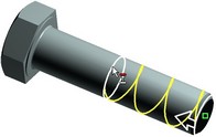
The offset values can be defined either by a numerical value in the property window or by hand in the 3D view window. In the latter case, move the pointer to the dragger defining the position of one of the thread ends. The pointer will change to ![]() (at the start of the thread) or
(at the start of the thread) or ![]() (at the end of the thread). After that, you can define the new position of the respective thread end by dragging the mouse with the depressed
(at the end of the thread). After that, you can define the new position of the respective thread end by dragging the mouse with the depressed ![]() . The property window will be reflecting the current offset value. If necessary, it can be adjusted by entering a new value. The way of defining the thread offsets can be modified either in the parameters dialog box or by using the automenu options:
. The property window will be reflecting the current offset value. If necessary, it can be adjusted by entering a new value. The way of defining the thread offsets can be modified either in the parameters dialog box or by using the automenu options:
![]() <A> Select thread start type
<A> Select thread start type
![]() <D> Select thread end type
<D> Select thread end type
Each of the options contains an enclosed list of choices for defining the thread start and end, respectively.
To define the start boundary of the thread, you can select:
![]()
From face start. This is the default setting. The offset for the thread start is counted from the start boundary of the base face. The start is considered the end of the face nearest to the pointer position of the time of selecting the face.
From object. The thread start offset will be counted from the additionally selected 3D object. Upon selecting this option, you need to specify the desired object.
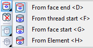
Define the end boundary of the thread as:
From face end. This is the default setting. The offset for the thread start is counted from the end boundary of the base face.
From thread start. The offset is counted from the start of the thread, thus defining the actual thread length.
From face start. The offset for the thread end is counted from the start boundary of the base face.
From object. The offset for the thread end is counted from an additionally selected 3D object. Upon selecting this option, you need to specify the 3D object.
The mode of defining "From object" can only be set by the automenu options.
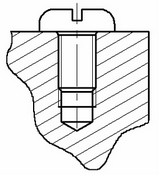
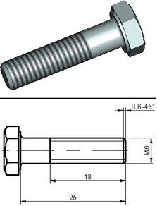
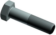
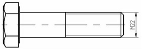
In the bolt example, one of the thread parameters is its length, counted from the end of the bolt stem. Often, the thread is applied to a face already trimmed by a chamfer. To account for the chamfer when defining the thread length, use the option "From object" for the start boundary and select the end face of the bolt stem or an element belonging to this face (such as a 3D node) as the object. The end boundary of the thread can be defined in this case as "From thread start", entering the value of the exact thread length as the offset.
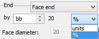
The amount of default offsets is defined among the model units (the command "ST: Set Document Parameters", the tab "3D"). It is possible to define the offsets in percent of the face length or of the distance between the start of the thread and the end of the face (if using the option "From thread start" for the end boundary of the thread).
When selecting any of the thread boundaries in the option "From object", the options for selecting 3D objects become accessible in the automenu:
![]() <V> Select points
<V> Select points
![]() <L> Select lines
<L> Select lines
![]() <U> Select planes
<U> Select planes
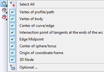
You can select any 3D elements as the object, that define a point, line or plane. Any of those options contains a list of filters for selecting 3D elements, that tune the selector for picking the desired geometry type. Use of those filters is described in details in the chapter "Basic 3D terms and principles of modeling with T-FLEX CAD 3D". To select a different object for defining the position of the thread boundary, simply repeat the selection. You can cancel relations between thread boundaries and selected objects by modifying the thread offset option in the automenu or in the property window.
To cancel the selection of the base face and the reference objects for the thread boundaries in one move, use the automenu option:
![]() <R> Cancel selection of all Faces
<R> Cancel selection of all Faces
Complete the thread creation by pressing the option ![]() . The thread will then be schematically displayed on the selected face.
. The thread will then be schematically displayed on the selected face.
Thread display on 2D projections
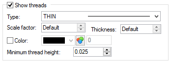
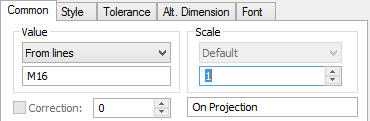
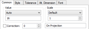
By default, the thread-marking lines are automatically created on 2D projections of bodies with threads. The line display is controlled via the projection properties, the tab "Lines". When dimensioning the thread lines, the thread notations are applied automatically. To cancel this mode (of creating a normal dimension), set parameter “Value” to “Auto”. By default the value is set to “From lines” for dimensioning the thread lines.
Hidden threads can be displayed on 2D projections by dashed lines, when the "Show hidden lines" mode is turned on. When creating a section or a local view, the thread is displayed in the usual way. In those cases, thread notations can be applied automatically when dimensioning thread lines.
Sections of the threaded connections require setting of the "Fill Element Outline" flag in 2D Projection parameters (see more details in "2D Projections" chapter). When flag is set, lines of the section view will be constructed correctly. Otherwise projection lines of bolts and holes will overlap each other due to interpenetration.