Rib


Rib |
|
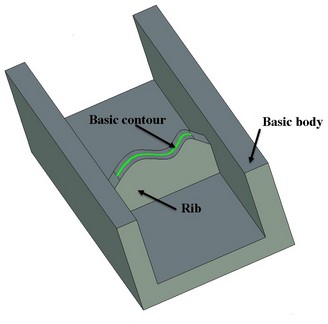
A rib is an element that is obtained by extension of a contour in the given direction until intersection occurs with the faces of the initial body.
Ribs can be created on the basis of closed as well as open contours. The result of execution of this operation is a solid body obtained with a Boolean operation of union of created rib with the initial body.
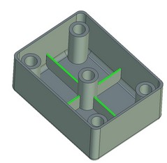
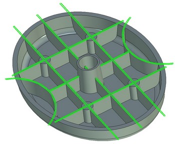
The user specifies direction of extension of the initial contour and its thickness. After selection of several contours a grid of ribs can be created. In this case the thickness for several objects is specified immediately for the entire grid.
Contour may consist of several parts. In this case one direction to solid body is specified for all parts of the contour.

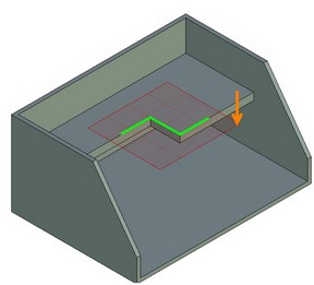
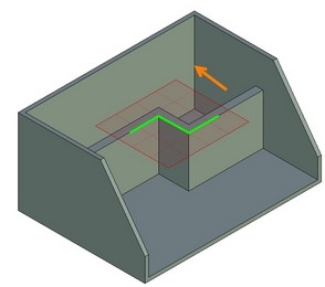
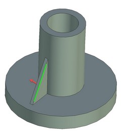
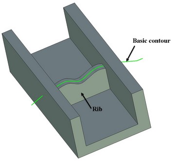
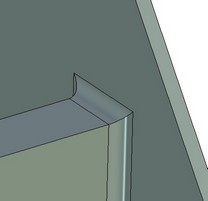
It is not necessary to limit rib contour with solid body walls. In most cases system can automatically determine the boundaries of the created edge. On the picture below the rib is limited with planes of the solid body faces.

Note that if borders can’t be automatically determined the construction of the rib will not be possible.

Creation of rib
Before construction of a rib it is required to create a contour that will define the shape of this rib.
To create a rib we use the “3ST: Create rib” command. This command can be invoked via:
Icon |
Ribbon |
|---|---|
|
3D Model → Modify → Rib |
Keyboard |
Textual Menu |
<3ST> |
Operations > Rib |
To create the operation, it is required to execute the following sequence of actions:
1.Select the source body;
2.Select forming contour;
3.Select direction of extrusion of the rib;
4.Specify thickness of rib;
5.Specify additional capabilities of the operation (not a necessary step);
6.Confirm creation of operation.
Selection of Source Body
To create a rib it is firstly required to select the source body. After invoking this command the following option will automatically be activated in the automenu:
|
<S> |
Select body |
Selection of contour
After selection of the source body the option of selection of the contour that defines the form of a rib being created is activated.
|
<С> |
Select forming contour |
As a contour we can select 3D profiles, faces, edges, paths, loops. If there is only one profile in the scene, it will be selected automatically.
After the first contour has been selected this option remains active, and if necessary you can select several contours.
When contour extends beyond the limits of the source body it is cut to the required size.
Contour which consist of several parts may create two ribs and more.
By using one contour we can specify two or more ribs.
Entire contour. When flag is set, rib can be created outside of the body using the closed contour.


All of the selected contours are displayed in the «Forming contours» tab in the command’s properties window.
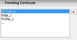
The ![]() button removes selected contour from the list.
button removes selected contour from the list.
Direction of Extension of Rib
Extension of a contour can be carried out in two directions:
●In the plane of contour
●Perpendicular to the plane of contour
Direction |
Position and shape of rib |
Result of construction |
Perpendicular to plane of contour |
Surface of a rib is formed by extension of contour in the direction perpendicular to its plane |
|
In the plane of contour |
Surface of a rib is formed by extension of contour in the direction of its plane. |
|
To choose the method of contour’s extension it is required to use the «Main parameters» tab of the command’s properties window.

Direction of contour extension is displayed in the scene as arrow- manipulator.
Contour Direction for a Straight Segment
If forming contour is specified by a straight segment, its positioning plane is determined automatically by the following rule. If segment presents part of a profile, system will use plane of the profile creation. If segment presents part of a path, positioning plane is defined by rotating the segment in global coordinate system to the nearest plane the segment coincides.
Contour extension direction is created according to the determined positioning plane.
To select contour extension direction manually, you need to use option:
|
<D> |
Select contour direction |
Next you need to select an auxiliary element. If you select object that specifies plane – face, workplane, etc., then the direction will be a normal to this plane. Alternatively, you can select object that specifies direction – edge, coordinate axis, etc.
Specified contour extension direction will affect all selected contours defined by the straight segments.
To cancel direction selection use option:
|
<K> |
Cancel direction selection |
Direction to Solid
In addition to contour extension direction, you can specify direction to solid. It determines which part of the half-space, created by contour, will be transformed into the rib.
Special manipulator is used to specify direction to solid. It indicates direction inside the rib body from the point located on the contour. If contour is open, the point is located in the center of the contour line. For closed contour, the point position is chosen arbitrarily. For convenience you can move this point along the contour.
Direction to solid can be defined individually for each contour. To change direction you need to move the manipulator, pulling one of its arcs.
The manipulator allows you to set the direction to solid manually. Thus, system does not need to determine correct direction automatically.
After the operation creation, all space between the walls of the source body and the contour in determined direction is converted into the solid rib of specified thickness.


Thickness of rib
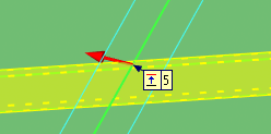
When forming a rib, new solid material is added in the direction perpendicular to contour extension plane.
The value of thickness can be specified in appropriate field of the «Main Parameters» tab of the command’s properties window or by means of manipulator.

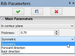
The direction of thickness adherence must also be specified for a rib:
●Forward direction. Direction coincides with the direction of the normal to the contour’s plane.
●Back direction. Direction is opposite to the direction of the normal to the contour’s plane.
●Symmetric. Thickness is added to the rib equally in both directions with respect to the plane of the contour.
|
|
|
Symmetric |
Forward direction |
Back direction |
Direction of thickness adherence can be selected from the drop down list on the «Main parameters» tab:
In case if the specified value of the thickness parameter becomes larger than the value of the contour’s length, the corresponding field will be renamed to ”height”.
Additional capabilities of operation
●Taper of Rib’s Faces. If it is required that the faces of the rib have a taper, the following actions must be executed:
1.Select direction of a taper by using the option:
|
<T> |
Set tapering direction |
When this option is enabled the geometric element is selected that specifies the direction of the taper.
2.Enable the «Taper» flag on the «Main parameters» tab of the command’s properties window.

3.Enter the value of the tilt angle in the field next to the flag.
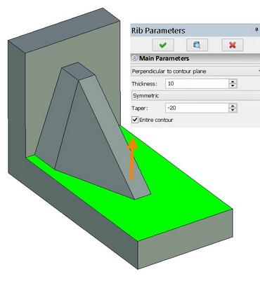
In the example the normal to the selected face serves as a geometric element that specifies the direction of the tilt.
To cancel selection of tapering direction use option:
|
<R> |
Cancel taper direction |
●Blending ribs. To specify parameters of ribs blending it is required to use the «Blend parameters» tab in the command’s properties window.

To smooth out the side faces of a rib on its ends it is required to enable the «Edges» flag and input the required value of blend radius in the field next to the flag.
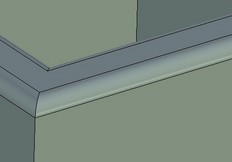
To smooth out intersections of a rib with the source body it is required to enable the «Intersections» flag and input the required value of blend radius in the field next to the flag.
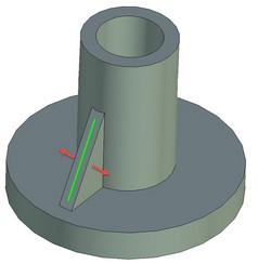
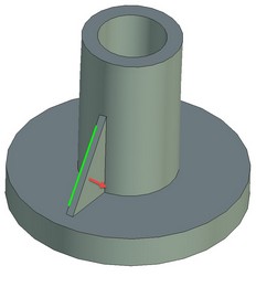
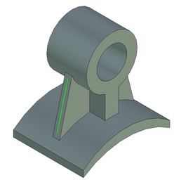
Separate body. Allows to create a rib as a separate body. The option, in particular, allows you to create welded structures using ribs. This method may be used for example when modeling welded structure of flange and pipe. |
|
In the “Option” section, you can set options for displaying auxiliary elements.

Option "Use draggers" allows you to enable/disable the display of manipulators that specify the direction to solid and rib thickness.
Option "Show labels" allows you to enable/disable the display of the labels that output rib thickness.

Rib Editing
To edit a rib use command:
Keyboard |
Text menu |
Icon |
|---|
<3EST> |
Edit > Operations > Rib |
|
|---|
To reset thickness and direction to solid, you need to select the rib in edit mode, and then use option:
|
<F4> |
Execute edit command |
In the “Forming Contours” section of the properties window, select contour and reset its parameters.

More information about this command can be found in the chapter "Editing".