2D Projections


2D Projections |
|
2D Projections. Creating 2D Drawings of the 3D Models
A 2D projection is a two-dimensional image located in the 2D window, obtained by projecting a three-dimensional model or its selected portion on the specified plane. Projections can be used for creating the necessary views on a 2D drawing, with their subsequent decorating, as well as for obtaining local views and sections. One can project whole bodies or even groups of bodies, as well as selected elements of the model, such as faces or edges. If you are working with large 3D models, use the method of creating 2D projections in a separate file. Projecting is also actively used in three-dimensional modeling for drawing on active workplanes bound to the topology of three-dimensional objects, for example, to faces or edges.
Types of 2D Projections
T-FLEX CAD allows creating 2D projections of the following types:
●Precise (Image Lines). The view of the projection of this type represents itself a collection of the graphic lines;
●Vector Picture. The view created on the projection of this type entirely corresponds to the type “Precise (Image Lines)”. However, in this case the graphic lines themselves are not created, and the projection is drawn as a picture. This mode allows a user to reduce the 2D projection generation time, and also reduce the memory usage required for creating a large number of graphic lines;
●Shading. The view of the projection is drawn in the form of shading which corresponds to the mode of the same name in the 3D window
●Rendering. The view of the projection is drawn in the form of rendering which corresponds to the mode of the same name in the 3D window;
●Wireframe. The view of the projection is drawn as a wireframe which corresponds to the mode of the same name in the 3D window. In this mode, the parameter “Remove Hidden Lines” is available depending on which the removal of the hidden lines is carried out or not.
Projections of the types “Precise (Image Lines)”, “Shading”, “Rendering”, “Wireframe” have the following limitations:
-it is not possible to hide (remove) separate elements (lines) of the projections or modify their parameters;
-it is not possible to project 3D construction elements (3D paths, 3D profiles). Only bodies (operations) can be selected for projection.
All types of 2D projections support the creation of the service elements based on the projection types. On the projection of the type “Precise (Image Lines)”, the service elements are attached to the projection lines, for the rest of the projection types – the service elements are attached directly to the elements of the 3D model.
Creating projections of all types is carried out similarly.
Creating 2D projection
To create a 2D projection, use the command "3J:Create 2D Projection". Call the command as follows:
Icon |
Ribbon |
|---|---|
|
Draw → 2D Projection |
Keyboard |
Textual Menu |
<3J > |
Draw >2D Projection |
Upon calling the command, the following actions are available:
![]() <1> Create three standard projections
<1> Create three standard projections
![]() <2> Create section view
<2> Create section view
![]() <3> Create additional view
<3> Create additional view
![]() <4> Create local section view
<4> Create local section view
![]() <5> Create set of standard projections
<5> Create set of standard projections
![]() <6> Create standard projection
<6> Create standard projection
![]() <7> Workplane projection
<7> Workplane projection
![]() <8> Projection by Projection
<8> Projection by Projection
![]() <9> Arbitrary View
<9> Arbitrary View
![]() <F> Select File with 3D Model to create Projection
<F> Select File with 3D Model to create Projection
You can also select the type of the projection to create in a combo box provided in the proper ties window
Before you begin creating drawings using projections, it is recommended that you determine the format of the drawing, how many pages it will occupy and what will be the scale on each page. All of these parameters are defined on the Page tab in the command Customize > Document parameters. . Each page uses its own settings. The settings can be modified at any time.
The general algorithm of creating a 2D projection includes several required and optional steps:
1. Define the projection direction (required) by one of the following ways:
- Using one of the options for creating standard projections (the options ![]() ,
, ![]() ,
, ![]() ).
).
- Automatically by the system, depending on the section line position, in the case of creating a section or local section view (the option ![]() ).
).
- From the direction of the detail view specified by the detailing element (the option ![]() ).
).
- Same as the direction of the original projection, when creating a local area view (![]() ).
).
- By a workplane (the option ![]() ).
).
- By 3D model elements, such as a flat face, using the set of additional options.
- By defining the directional vector of projecting and the rotation angle about this vector in the projection parameters.
- Along the projecting direction of an existing 2D projection (the option ![]() ).
).
In most cases, the system attempts to determine the type of the projection being created by the first selected element. For example, if a section is picked, the system will offer creating a cut; picking a hatch prompts a local area view; picking a face – a general view, etc.
2. Define the attachment point in the 2D window (optional). Normally, you need to specify the location on the drawing via a 2D node or free point at which the projection is to be created. In this case, the projection to be created is shown as a box indicating the projection extents.
3. Select section to be used on the projection (optional). This step is necessary when creating a local view or section.
4. Select bodies to subject to the section (optional). This step is necessary when creating a local view or section affecting only selected elements of the model being projected.
5. Select model elements to project (optional). By default, the whole 3D scene is projected in its current state; however, it is also possible to project separate Bodies, operations or specific topology elements (faces, edges).
6. Define projection parameters (optional). Some properties, such as scale, can be specified in the "2D Projection Parameters" dialog box or in the properties window.
7. Select the type of 2D projection being created: “Precise (Image Lines)”, “Vector Picture”, “Shading”, “Rendering”, “Wireframe”;
8. Confirm the input (required). As in any 3D command, the element creation must be confirmed upon competing definition of all parameters. This step is possible, when the option becomes accessible in the automenu:
![]() <Y> Finish input
<Y> Finish input
Creating standard views
The simplest way of quickly obtaining 3D model drawings is creating one of several standard projections (which is often sufficient).
Creating three standard projections
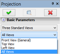
For convenience, the capability of creating the three most common used standard views is separated in the special command, providing for the Elevation ("Front") View, Plan ("Top") View and Side ("Left") View:
![]() <1> Create three standard projections
<1> Create three standard projections
Upon selecting the option, the automenu offers the group of commands for creating the set of standard projections:
![]() <M> Click to select 2D Projection attachment Point
<M> Click to select 2D Projection attachment Point
![]() <K> Break projection link with Front view
<K> Break projection link with Front view
![]() <E> Select model elements to project
<E> Select model elements to project
When creating standard views, the automenu has several additional options common for all types of projection (options for creating broken views and handling sections). Working with those will be described separately.
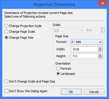
If overall size of a projection exceeds the page size, system will open the dialog box with options for correcting inconsistency between the projection and the page. The dialog box offers the following options:
●Change projection scale;
●Change page scale;
●Change page size;
●Don’t change anything.
All correctional parameters are calculated automatically. User can agree with them or set custom values.
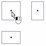
Next, you need to position the projections on the drawing. Three blue frames appear in the 2D window, attached to the pointer. These frames mark the extents of the projections being created. Currently, all three projections are selected. Position a particular view, selected first. View selection is done by clicking once within the blue box (the second click activates the option of positioning the view The mechanism of positioning a projection on the drawing is common to all types of projections; therefore, we will skip its detailed description in the future. |
|
If the front (main) view is being positioned, the rest of the views maintain their position with respect to the main one. When adjacent views are positioned, the projective relation is maintained with respect to the main view. The projection centerpoint snaps to the attachment point. To assign a specific 3D model element as the attachment point, such as a 3D node or vertex, you need to use additional options for creating the projection that are made available by the option |
|
By default, the adjacent views maintain the projective relation with the main view. This relation can be broken by the option |
|
Identical parameters are set for all views created simultaneously. In the case when different settings are required for a particular view, select it in the properties window. After that, you can define the specific elements to be projected on this view or select a 3D section to be used on the view. In some cases, this approach to creating views can save time.
If necessary, one can select model elements to project using the option ![]() . Selection of bodies for projecting is described in details below, as this command is common for all types of projections (see the section "Selecting bodies for projecting").
. Selection of bodies for projecting is described in details below, as this command is common for all types of projections (see the section "Selecting bodies for projecting").
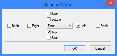
Creating the set of standard views
This command is different from the previous one in that you can define an arbitrary number of standard views. All other steps are identical. Create a set of standard projections using the option:
![]() <5> Create set of standard projections
<5> Create set of standard projections
Upon calling the option, a dialog box appears for defining the projections to obtain.
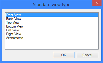
Creating one standard view
Create the one standard view using the option:
![]() <6> Create standard projection
<6> Create standard projection
In the list of the standard views, select the one to be created. The type "Axonometric View" is added to the list of the standard views. Elements of this list are also present in the properties window, in the overall list of the 2D projection types.
As usual, first, position the projection on the drawing - select the attachment point. In this case, you can attach the view being created to an existing 2D projection. You can define the relation between the view and another projection using the option ![]() . Once the option is engaged, select one of the projections. Such a relation allows creating a "standard" view with respect to any arbitrary projection selected as the main view, that is, the "Front View". The relation can be broken by the option
. Once the option is engaged, select one of the projections. Such a relation allows creating a "standard" view with respect to any arbitrary projection selected as the main view, that is, the "Front View". The relation can be broken by the option ![]() .
.
After attaching the view to the drawing, you can select elements to be projected using the option ![]() .
.
Creating additional view
The directional view element is often used for decorating drawings. It can also be used for creating a projection. In this case, the projecting direction will be determined by the arrow and the projection nearest to the arrow. The mode of creating an additional view is turned on by the option:
![]() <3> Create additional view
<3> Create additional view
Next, select a directional view element. The nearest to the arrow projection will then be highlighted. The system will use that projection as the main view. The additional view will be constructed relative to the main view. By default, the additional view maintains the relation with the main view. This relation can be broken using the option:
![]() <K> Break link of Projection with Front View
<K> Break link of Projection with Front View
The final steps are positioning the projection on the drawing and, if necessary, selecting the model elements to be projected.
Creating local view or section
Before beginning with creating a local view or section, have certain elements available. First, you should create in advance either a 3D section (the command 3SE:Construct Section), or a 2D section on the drawing (the command SE:Create Section). Note that the latter element should be constructed on one of the existing projections. Only in this case it can be used for creating sections.
The mode of creating a local view or section is set using the option:
![]() <2> Create section view
<2> Create section view
Next, you need to select a 2D section on the 2D drawing, or a 3D section. The normal to the section plane defines the projection direction. The elements are selected using the options:
![]() <S> Create 2D Projection based on 3D Section
<S> Create 2D Projection based on 3D Section
![]() <L> Create 2D Projection based on 2D Section
<L> Create 2D Projection based on 2D Section
Next, define the projection attachment point in the 2D view using the appropriate options.
Breaking or reinstating the relation between the projection being created and the specified section is done using the option:
![]() <К> Break link of Projection with Front View
<К> Break link of Projection with Front View
After that, you can select elements for projecting and elements to be sectioned. Selection of elements for projecting is done in a conventional way – by the option ![]() . By default, the section is applied to all bodies selected for projecting. However, this is not always required. There is a provision for specifying the list of operations or Bodies to be subjected to the section.
. By default, the section is applied to all bodies selected for projecting. However, this is not always required. There is a provision for specifying the list of operations or Bodies to be subjected to the section.
When creating a local view or section on the basis of 2D section view, the presence of a gap on the initial projection is taken into consideration.
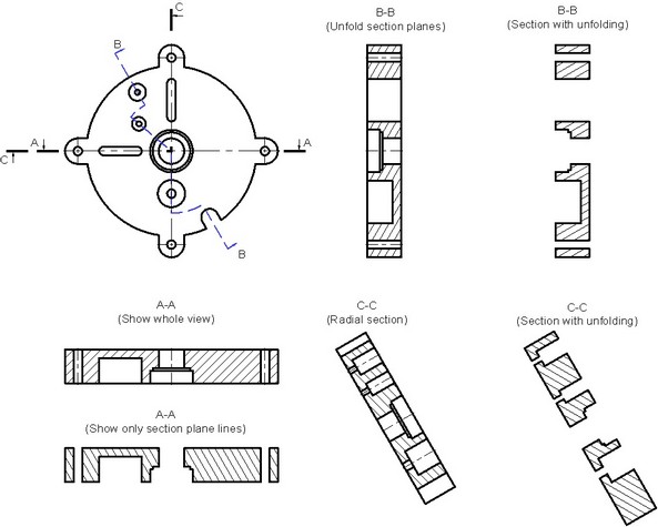
The parameters for controlling the sections that are in use are joined in one group and positioned on the tab "Sections" of the properties window. The used sections are displayed in the list "Use Sections". This list displays the names of 3D sections or IDs of section notations. To select an additional 3D section, placed the pointer at an empty line marked by an ellipsis, and then select the desired element in the model space or in the "3D model" window. Alternatively, a section can be selected by the automenu option: The type of the projection created by using sections can be selected from the combo box: Section View, Only Section Planes, Unfold/Radial Section and Section with Unfolding. Unfolding can be done only if a composite section was used (a one containing multiple segments).
Each of the sections can be applied to all objects being projected at once, or just to the specifically selected objects among those being projected. The list of operations/Bodies subject to the selected section is displayed in the "Use Sections" list. To select elements, use the list in the properties window or the automenu option: |
|
This option allows selecting not only operations, but also Bodies.
The way of using the list of bodies can be set in the combo box. The available options are "Selected elements", "All elements excluding selected", "All elements", “From section parameters”. The “All elements” option is set by default in the used if the elements list is empty. When choosing the ”From section parameters” option the section application rules are taken from the 3D section properties.
It is possible to specify beforehand that a 3D fragment will NOT be cut by a section when creating a section view of an assembly. This option can be set in ST: Set Document Parameters command and is usually used in the libraries of standard parts.
The option "Unfold section planes/Radial section" can work in one of two modes. This depends on what type of multiple-point section is used in the case. If a multiple-point section is composed of all straight segments, the whole section will be fully unfolded. If at least one segment of a multiple-point section is a circular arc, then the radial section mode turns on. In this case, all arcs are skipped when unfolding the section.
The option "Section with unfolding" always creates full section unfolding, even when the section contains circular arcs.
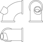
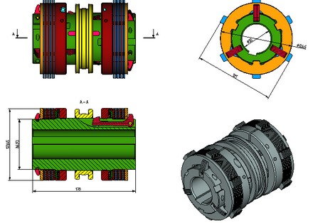
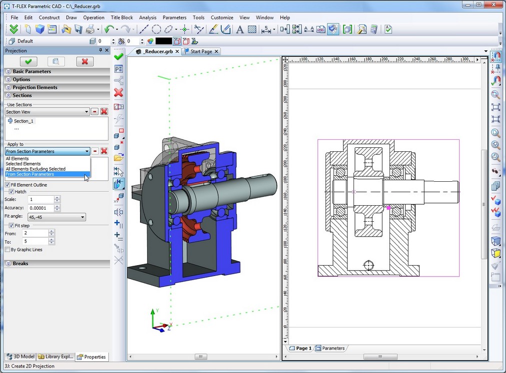
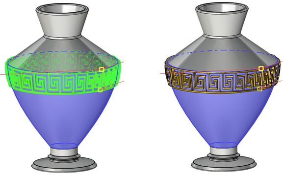
In the following example, two sections are created, both based on the main view. In the first case, the section was applied to the shroud only, while in the second case – to all bodies.
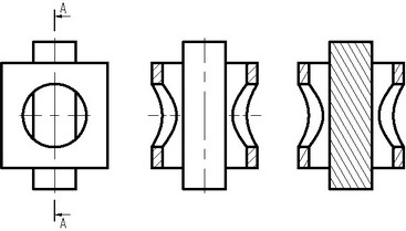
The following additional settings are provided in the sections handling group of parameters:
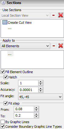
Fill Element Outline. This setting helps correctly draw threaded connections in which elements penetrate each other (due to the specifics of this type of connection). Additionally, some elements of the threaded connection (for example, the standard elements) can be exempted from section.
Hatch section planes. This parameter defines whether to hatch the section or local view. The precision of defining the hatch contour can be set in the provided box.
Scale. The hatch scale
Accuracy. This is the accuracy of tracing the hatch contour. Adjusting this parameter helps in complicated cases, when the system cannot hatch the contour under the previously specified accuracy.
Fit angle. Sets the choice of automatic hatch angle definition for crosscut parts. The combo box provides two choices: «45, -45» only and «30, 45, 60, -30, -45, -60»
Fit step. Sets the upper and lower limits on the values, within which the system automatically picks up a hatch step. The step size is determined relative to the area of the hatch contour.
By Graphic Lines. This option is available only for projection of the type “Precise (Image Lines”). When this flag is on, the hatch on cuts/sections is formed by graphic lines of the projection, when it is off – by faces which appear on the projected body as a result of applying 3D section.
By default this flag is turned off, i.e., the hatches are created by the faces of the section (since the graphic lines on the projection do not always form a closed contour due to loss of accuracy while projecting).
It is recommended to turn on the flag “By graphic lines” if the hatch being created will be used later for construction of 3D profile or local section view.

Managing hatch properties in cuts and sections
The drawing standards require that all cut or sectioned parts are hatched in a certain way. If the material the part is made of requires hatching by a special pattern, then the appropriate «pattern» hatch type must be set in the material properties. In all other cases, the material is hatched in the sectioned areas by the repeating lines with a certain slope and step. If multiple bodies are involved in a section, then the hatch slope and step must differ across them. When creating a cut or sectioned for the first time, the system automatically picks different hatch properties (slope angle and step) for different parts. Note also that the hatch parameters that were once picked for a certain part (operation) are automatically remembered in the model, and the same hatch parameters will be used for the same part in any cuts or sections on other views.
Those hatch properties are stored together with the original operation and are propagated on child operations, whenever those have the flag set, «Attributes from source operation»
Nevertheless, the user can modify hatch properties in a cut at any time by editing its parameters. Upon confirming changes to hatch properties, the system will query you, offering two choices for the continuation.
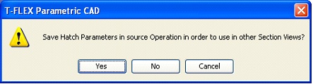
If the user responds «Yes», then the specified new parameters of the hatch slope angle and step will be saved in the model and will later be used for this part in all cuts and sections in which the part is involved. If the user responds «No», then the hatch will assume individual settings and will not depend on the operation properties in the future.
To revert the individually specified hatch properties back to the properties assumed from the 2D projection, one would need to right-click this hatch ![]() and in the coming up context menu select the item «Properties from Projection».
and in the coming up context menu select the item «Properties from Projection».
Another useful item in the context menu of a cut hatch is «Do not apply section». Upon calling this command, the operation for which the cut hatch was created will be added to the list of the operations that shall not be subjected to sectioning in the given projection. After that, the projection will be automatically rebuilt.
Creating local section view
This command allows creating local section views on an existing projection:
![]() <4> Create local section view
<4> Create local section view
The boundaries of the local section view are defined by the hatch contour. The latter must be created before creating the local section view. To select the hatch, turn on the option:
![]() <H> Select Hatch as boundary of local section view
<H> Select Hatch as boundary of local section view
Upon completing creation of the local section, the hatch becomes invisible, while screening out a portion of the main projection. The lines of the local section will be drawn with higher priority, than those of the hatch and the main projection.
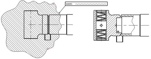
Geometry of the graphic lines bounding the contour of the original hatch can be taken into consideration when defining the boundaries of the local section view. For example, if the hatch contour pattern was set as waves, the boundaries of the local section view will also have waves pattern. A user can toggle on/off the lines type switch found in the parameters of the local section view.
Next, define the position of the section plane. The plane normal automatically coincides with the viewing direction of the main projection – the one used for creating the local section view. Thereafter, position the view plane either by a 3D node or by a 2D node in another projection. For example, if you are creating a local section on the Left View, then the 2D node can be selected in one of the adjacent standard views: Front, Top, Bottom, Back.
The 2D or 3D node can be selected using the options:
![]() <3> Select 3D Point, defining section position
<3> Select 3D Point, defining section position
![]() <2> Select 2D Node on other Projection, defining section position
<2> Select 2D Node on other Projection, defining section position
The local section view is automatically tied to the projection on which it was created. However, this tie needs to be broken in some situations, in order to attach the local view to the drawing at a different location. The option to break the tie is:
![]() <К> Break link of Projection with Front View
<К> Break link of Projection with Front View
Once the tie is broken, the following option is available for attaching the projection to the drawing (an unconstrained attachment or snapping to a 2D node).
![]() <M> Click to select 2D Projection attachment Point
<M> Click to select 2D Projection attachment Point
When creating a local section view, we recommend selecting specific model elements to be projected. Selecting the elements that actually fall in the area of the local section view speeds up regeneration of the projection.
Creating projection on a workplane
The projection on a workplane is used when working with active workplanes. For example, when creating a new workplane based on a flat face, the selected face can be automatically projected on that workplane. The command of constructing the projection on an active workplane can be called by the icon ![]() , located on the main toolbar in the button sets “Workplane” and “Workplane (Sketch)”.
, located on the main toolbar in the button sets “Workplane” and “Workplane (Sketch)”.
If the workplane is present in the 2D view, sometimes it is convenient to use that workplane for projecting model elements. The following the option is provided for this purpose:
![]() <7> Workplane projection
<7> Workplane projection
The workplane can be selected either in the 3D window or on the 2D view. The projection will be created in the same page of the drawing as the selected workplane. You do not have to explicitly position the projection on the drawing. The position of the projection is determined automatically, since each workplane has its specific position in the 3D space. The objects are projected on the workplane along its normal direction.
Projecting 3D point on workplane
The capability of creating a 2D node on a workplane as a projection of the 3D point is not directly related to the 2D projection construction command, nor it has to the T-FLEX CAD "2D projection" element.
Creating a 2D node as a projection of a 3D point is used when working with active workplanes, often together with the command for constructing a 2D projection on a workplane the command for creating 3D nodes - projections of 3D point saves computational resources of the computer when it is not necessary to create a conventional path 2D projection.
The icon ![]() that launches the command of constructing a 2D projection node is located on the main toolbar (in the sets “Workplane” and “Workplane (Sketch)”) and is available only when working with the active workplane. To create a projection node, select a 3D point in the 3D window.
that launches the command of constructing a 2D projection node is located on the main toolbar (in the sets “Workplane” and “Workplane (Sketch)”) and is available only when working with the active workplane. To create a projection node, select a 3D point in the 3D window.
General case of creating 2D projection
The most general approach to creating a 2D projection is supported by the “Arbitrary View” ![]() item. Upon turning on the option, the following actions are available:
item. Upon turning on the option, the following actions are available:
![]() <M> Click to select 2D Projection attachment Point
<M> Click to select 2D Projection attachment Point
![]() <F> Select Plane to set view direction
<F> Select Plane to set view direction
![]() <N> Select 3D Point for attachment point
<N> Select 3D Point for attachment point
![]() <K> Cancel setting of view direction.
<K> Cancel setting of view direction.
![]() <S> Select 3D Sections to apply
<S> Select 3D Sections to apply
![]() <E> Select model elements to project
<E> Select model elements to project
First, define the position of the projection on the drawing – select the attachment point. The axonometric projection of the whole scene is created by default in the world coordinates. The projection of the world coordinates origin is snapped to the point on the 2D view selected at the previous step. A 3D point can be selected to define the point in the space for aligning with the fixing point on the projection.
The projecting direction can be changed by one of the following means:
- Select projection plane . The projecting direction will be defined by the normal to this plane. To select a plane, use the option:
![]() <F> Select Plane to set view direction
<F> Select Plane to set view direction
- Define the viewing point in the properties window. It can be defined using coordinates or by selecting one of the standard or custom views.

The coordinates of the view direction can be defined in the properties window. The X, Y and Z are entered in the respective input boxes of the end point of the direction vector. The start point of the vector is the origin of the world coordinate system. A user-defined custom view can be loaded with the help of the button "Load" ![]() . A custom view can be saved via the command "3VP:Set View Parameters".
. A custom view can be saved via the command "3VP:Set View Parameters".
Angle is the parameter defining the rotation angle of the 2D projection on the 2D view about the fixing point. The positive values define rotation in the counterclockwise direction.
Defining the coordinates and the rotation angle is possible only after creating an arbitrary view. When creating other types of view with projective relation, such as standard or section view, the coordinates are defined by the system, and so these fields may be blocked.
Creating a 2D projection by an existing projection
To create such a projection, the ![]() option is used. Upon selecting this mode, the following options become available in the automenu:
option is used. Upon selecting this mode, the following options become available in the automenu:
|
<V> |
Select source Projection to specify Parameters |
|
<E> |
Select model elements to project |
|
<A> |
Select all Solids in current scene |
|
<F> |
Select File with 3D Model to create Projection |
|
<Ctrl+S> |
Select 3D Sections to apply |
|
<Ctrl+O> |
Select Operation to apply 3D Section |
First, the source 2D projection is to be specified in order to use its properties for the projection being created. The new 2D projection will match the source one in its position, orientation, and the use of broken views. The rest of the projection parameters can be edited: you can change the list of the objects to be projected and the applied sections, the projecting (mapping) method, available line styles, and hatch parameters.
The newly created 2D projection is automatically assigned the priority which is by five points greater than the source projection. In addition, the flag “Create Outlined Area” is set in the properties of the new 2D projection (see the section “2D projection parameters”).
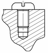
This method of creating a 2D projection can be used to construct projections of threaded connections where both the “screw” and the “nut” of the connected pair are sectioned. The thread lines of both the “screw” and the "nut" will be overlapped on the projections in which both parts are simultaneously sectioned. To insure the correct appearance of a threaded connection, what one can do is originally create the projection of the sectioned “nut”, and then create another 2D projection based on the first one, where you specify the “screw” only in the “to be projected” list.
Selecting elements for projecting
By default, that is, when nothing was selected, the whole scene is assumed selected for projecting. The option "Full scene" projects all operations visible in the scene at the time of regeneration, regardless of the number of the operations that were in existence at the time of creating the projection. New 3D elements cannot be created based on such projections (due to possible topology change or recursion), as prompted by the system warning at the time of creating the projection.
The elements need to be selected in the cases, when only specific elements need to be projected, rather than the whole model (particular operations, Bodies or construction elements/topology elements), or if the projection is intended for creating 3D elements. Besides, often happens, that some model objects are simply not visible on the projection because those were screened out by other bodies. For example, some parts may be inside a shroud. In this case, it is useful to exclude from projecting the objects that are not visible anyway. This will benefit in saving regeneration time of such a projection.
To select specific model elements, use the option provided in any mode of creating projections:
![]() <E> Select model elements to project
<E> Select model elements to project
This option has a pulldown list of filters for selecting the desired objects. Allowed for selection are Body, operations, 3D profiles, 3D paths, faces, edges and loops. The set to filter options for selecting objects is duplicated on the system toolbar. When activating the option |
|
It is also possible to activate the mode of selecting the elements for projection with the help of dialog of properties window. For that, it is sufficient to place the cursor in a free line of the list marked by dots and the option ![]() will be turned on automatically.
will be turned on automatically.
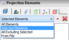
For each type of the selected elements the user can specify the method of projecting: -All elements – all elements of the given type in the scene will be projected; -Selected elements – only selected elements of the given type will be projected; -All except selected – all elements of the given type that has not been selected will be projected; -From file (only for Bodies and operations) – this option is set if projected operations and Bodies are selected from external file (see Section “Construction of 2D projection from model in external file”). When selecting this method, the option of selecting a file |
|
-Same as in operation (only for welded joints) – method of projecting welded joints will depend on the method set for operations and Bodies. If “All elements” is set for operations, all welded joints will be projected. If any other method is set for operations, then welded joints are not projected.
By default, for Bodies and operations the mode “All elements” is set, whereas for profiles, paths and coordinate systems – mode “Selected elements”. For geometric elements (faces, edges, loops) the method of projection is not specified (only selected elements are always projected).
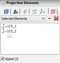
Projection of coordinate systems has certain specific features. The coordinate systems are projected on top of the entire 3D model without taking account of visibility. Projection lines of the coordinate systems are ignored when determining the boundaries of the projection.
Projections of the coordinate system are formed from three graphic lines with arrows. The color of each line-axis coincides with the color of the corresponding axis of the global coordinate system in the 3D scene. The style of the lines can be modified as for the standard graphic lines of the drawing. The length of the coordinate system axes is controlled by the parameter “Size|Coordinate System” in the dialog of the command “ST: Set document parameters”, tab “3D”. Projection of global coordinate system is specified separately with the help of “Global CS”. Selected method for projection of LCS does not affect projection of global coordinate system. |
|
The automenu provides a separate option for quick selection of all operations currently present in the 3D scene:
![]() <A> Select all Solids in current scene
<A> Select all Solids in current scene
The difference between the behaviors of the option "Select all Solids in current scene" and that of the mode of projecting the whole scene can be described as follows. The list of all operations selected in the 3D scene is formed at the time of using the option and stays unchanged unless intentionally modified. Therefore, the new bodies added to the scene do not appear in the list of the elements to be projected.
Constructing a 2D projection using a model from an external file
The mode of constructing a projection by a model from an external file is useful when working with complex 3D models and assemblies, in which cases you can significantly save the computational resources by avoiding the 3D model recalculation. When creating a 2D projection, the system takes from the external file only geometrical data saved in this file. It is also possible, if necessary, to compose a single drawing from different 3D models (different versions, individual fragments, etc.).
The option to select an external file to construct a projection is available in the command's automenu:
![]() <F> Select File with 3D Model to create Projection
<F> Select File with 3D Model to create Projection
If the user calls the command to create a 2D projection, but no 3D model is present in the current document, then at the beginning this will be the only option in the automenu. Upon calling this option, the standard dialog window to select the file will appear. Once you selected a file with the 3D model, all the rest of the options to construct the projection would become available in the automenu. After that, the projection is constructed as usual. At the same time, there are restrictions on selecting elements to map (project). In this case, it is always the entire 3D model contained in the selected file that will be mapped (projected).
If it is necessary to create several projections based on an external file, you do not have to select it over each time. When constructing related views (a related standard view, cuts and sections, arrow views), the data about the 3D model is automatically accessed from the initial projection.
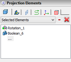
The information about the used external file is recorded in the 3D model tree next to the 2D projection name. If you right-click on the 2D projection ![]() , then you will see in the context menu the command to open the file, which it uses. The name of the file used to construct the 2D projection can be found on the "Elements" tab of the «2D Projection Parameters» window.
, then you will see in the context menu the command to open the file, which it uses. The name of the file used to construct the 2D projection can be found on the "Elements" tab of the «2D Projection Parameters» window.
The mode of constructing a projection based on the model from external file can be also activated by setting the method of projection “From file” in the group of the properties window “Elements” for Bodies and operations. Simultaneously, the option ![]() will be activated automatically.
will be activated automatically.
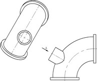
Creating broken view on projection
When creating long parts, it is often necessary to limit the part view to a certain portion to keep the drawing compact. T-FLEX CAD provides a tool for creating projections with broken view of the three-dimensional parts. The broken view can be created for all types of projections, except for the local section view and the unfolding section view.
Pay attention to the following details when working with broken views:
●When attaching a radial dimension or both legs of a linear dimension to lines of such projection or their children, the system automatically adjusts the dimension to obtain the true value.
●If the broken view was created in an already existing projection (when editing it) with some elements attached to it, such as dimensions, then these elements may get lost view to changes in the projection topology after creating the broken view.
If you create a new projection on the basis of the projection with a break, the break from the main projection will be copied to the dependent projection.
The option for creating the broken view on a projection is available in many modes of creating projections:
![]() <B> Add or edit Broken View
<B> Add or edit Broken View
![]() <V> Add horizontal break
<V> Add horizontal break
![]() <H> Add vertical break
<H> Add vertical break
![]() <R> Enter angle
<R> Enter angle
The reduction can be performed only in two orthogonal directions. The number of breaks in either direction is unlimited. A break is defined by a rectangular area. Two of its boundaries are determined by the extents of the projection, while the other two are defined by the user using the mouse and the appropriate options.
The rectangular area of the break is hatched by the lines at the time of creating and editing, the lines direction indicating the direction of the reduction (orthogonal to the breaking lines). The preview image of the projection is drawn in blue lines.
The following diagram shows an example of a projection with a broken view.
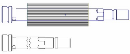
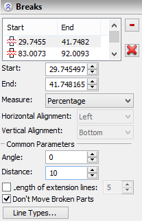
Also additional settings of broken views are done with the help of the properties window. Each broken view is added to the list of broken views in the properties window. Elements of this list are preceded by the icons marking the break direction (vertical/horizontal). Each broken view has properties defined, that determine the placement of the break lines on the projection. Initially, these properties are predefined automatically, as soon as the user selects a break location by the mouse. If the values are defined by variables then the respective variable name will appear in brackets next to the numerical value. Breaking lines position can be defined by absolute numerical values (the parameter "In model units"), or in percent (the parameter "In percents"). Start. This value defines the position of: left boundary - for a horizontal break, or the bottom one - for vertical. End. This value defines the position of: right boundary - for a horizontal break, or the top one - for vertical. With the mode "In model units" turned on, the start and end values can be defined by variables. Distance between the break lines defines the distance between the pieces of the broken projection. |
|
Angle. This parameter defines the angle of rotating the break lines with respect to the vertical/horizontal (according to the direction of the break). The positive direction is counterclockwise.
The angle can be also specified with the help of the option ![]() . After enabling this option, the line defining the initial boundary of the break (it is shown with red color) will play a role of a dragger. To specify the angle of rotation, it is enough to bring the cursor to this line, press
. After enabling this option, the line defining the initial boundary of the break (it is shown with red color) will play a role of a dragger. To specify the angle of rotation, it is enough to bring the cursor to this line, press ![]() and move the boundary by a desired angle.
and move the boundary by a desired angle.
Length of extension line. If the flag is cleared, then the breaking lines on the projection are restricted by the intersection points with the body. Otherwise, the breaking lines extend from one end of the body to the other end and beyond its limits by the "Length of extension line".
Don’t move broken parts. When the flag is on, projection lines, remained after applying the breaks, don’t change their location.
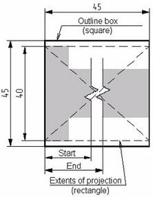
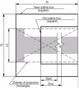
The following to parameters are intended for controlling the position of the break and its behavior with the model and the projection modifications. Those are available only if the break is defined "In model units". Horizontal binding (Left, Center, Right). Vertical binding (Bottom, Center, Top). To describe how these parameters are used, we need to introduce the concept of the "outline box". The center of the outline box is located in the center of the circumscribed rectangle of the projection. The outline box is a square, whose line length is equal to the length of the longer side of this rectangle. It is not displayed on the screen. |
|
The outline box is always are calculated on the projection regeneration. Therefore, a new outline box is generated as the projection dimensions change. An important fact is the distance defined by the parameters "Start" and "End" is always counted from the lower-left corner of the old outline box. The parameter values for the horizontal\vertical attachment defined a way of positioning the old outline books with respect to the new one. Suppose, for example, that the right center attachment is specified. This means that, after calculating the new outline box, the right side of the new box will be snapped to the right side of the old box, while the centers of both boxes will be placed on the center line of the part. The breaking lines are always constructed with respect to the lower-left corner of the old outline box. |
|
To set up the properties of the lines of a break's boundaries, call an additional dialog. To launch it, press the button [Line Types] in the properties window.
Show break lines. The option allows to hide break lines on the projection.

Broken lines type. The break in the projection can be outlined by lines of different types. This can be a straight-line, a waves, or a polyline. The waves and the polyline are provided the parameters Amplitude and Period. The units are same as the model units.
Keep in mind the specifics of the broken view projection creating mechanism. When generating the projection, the program internally creates a cut according to the specified break type. Therefore, the more complex the breaking line, the longer it takes for regeneration of a broken view projection.
The parameters Scale factor, Thickness and Line Type in this tab define the style of the breaking lines.
When creating a new broken view, the breaking parameters can be copied from an existing projection. Upon pressing the button ![]() , the system waits for selecting a projection, whose breaking parameters will be copied to the projection being the defined. This is a one-time action. That is, when modifying the breaks of the original projection, the breaks on the projection to which they have been copied are not modified.
, the system waits for selecting a projection, whose breaking parameters will be copied to the projection being the defined. This is a one-time action. That is, when modifying the breaks of the original projection, the breaks on the projection to which they have been copied are not modified.
Type Selection for Created 2D Projection
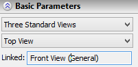
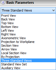
The type of a 2D projection being created (regardless of its creation method) is set in the command's properties window, in the group “Basic parameters”. The projection type is selected from the drop down list. |
|