Parameters of 2D Projection


Parameters of 2D Projection |
|
Some parameters of a 2D projection can be defined in the properties window at creation or editing. Additionally, the parameters dialog box can be accessed at any time from the context menu, or at any time while editing, when the option is accessible:
![]() <P> Set entity parameters
<P> Set entity parameters
"General" tab

Name. The following default names are assigned to 2D projections: Projection_0, Projection_12, etc.
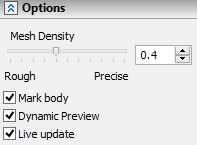
Update. This parameter defines how the projection will be updated.
- Auto (on any changes to model).
- Manually and on full regeneration (when choosing the command "Update 2D Projection" or upon full model regeneration). These settings make sense only when dealing with complex models, whose full regeneration takes considerable time.
Regeneration of “Vector picture” projection, in case of manual regeneration or regeneration on request, is carried out in background mode. When starting up regeneration, 2D projection view on the screen is replaced with a simplified view (similar to the view displayed in the 3D window in the mode “Quick hidden lines removal”). After that, they user can work with the system, for example, detail a drawing based on this projection. In parallel, the accurate regeneration of the projection will be performed simultaneously. When the regeneration is completed, the simplified picture of the projection is replaced with the results of the accurate calculation.
This approach allows the users to simplify the work with projections having long regeneration time. After creating and editing the projection, the users can continue working with the system right away, not awaiting the completion of projection recalculation.
Penetration.
●Ignore penetration of bodies. Bodies intersection is not considered.
●Consider penetration of bodies. When projecting a group of mutually intersecting bodies, you can turn on the body intersection analyzer. With the parameter is set, the system will build the projection, taking into the account the intersection of bodies. It will increase the time of calculating the projection.
●Define intersection of bodies. Allows you to create accurate isometric projections with a section.
Recognize straight lines. Recognize circles. These parameters turn on special algorithms that recognize straight segments or circles (circular arcs) within some tolerance limits. This is necessary in the cases when complex geometry is being projected. For example, projecting a variable-radius blend creates a polyline. With this option turned on, the polyline is replaced by a circular arc. The resulting arc can now be dimensioned. When these options are used, there is some loss in the projection accuracy. This may sometimes cause problems with automatic hatching of the sections and local views. This is due to rips that might occur in a contour, preventing the contour from hatching. A special option is provided to deal with the problem by controlling the accuracy of searching hatch contours (see the tab " View").
Variation. The option allows to to set link between the model configuration and the projection. Using the option you can create projections for each variation existing in the assemly. To specify a link, select the variation from the drop-down list.
Exploded View Scenario. The option is available only if there is at least one exploded view scenario. The projection is constructed using transformations from the selected exploded view scenario.
Simplify geometry. When the flag is set, Simplify model operation is performed before projections creation. This option is turned off by default, because it increases projections creation time. The option must be turned off when creating a projection of a sheet metal part unbending, for showing smooth edges of unbent areas. Option for showing smooth edges is located on in the Lines tab of projection parameters. When the option is active, splines are replaced with more simple geometry. You can create dimensions for it.
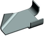
Original part Simplified projection Bend areas are shown
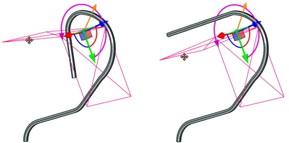
Save information for 3D dimensions. This parameter allows creating "spatial" dimensions on nonstandard and perspective views (such as the axonometric view).
Consider Welds. This option enables the display of weld seams created on the 3D model.
Fill Welds. This parameter enables the mode of filling the side strips of the weld seams with a color.
Geometry Search. If this flag is set on, at recalculation of a 2D projection, the search of service elements on the projection is performed by the geometry of the projection, and not by model IDs.
When searching by geometry, the old location of the original projection element is taken (line, arc, etc.) and within the tolerance the nearest element of the same type is sought for. The identification search is performed regardless of the geometry by the projection elements internal ID formed during the history of the element creation.
It is recommended to use geometric search when the model was subject to significant modifications and the usual search does not produce results (for example, upon updating the projections of the imported geometry after modifying the imported model with an external application).
Create Outline Area. This option constructs an invisible outline hatch on all projected bodies with the priority of one point less than the priority of the projection itself. As a result, you can overlap some projections with other projections.
This option doesn't work or works incorrectly in the case when paths, edges, faces, or loops are selected for projecting, or if the projection method without the removal of hidden lines is specified. This option doesn't work for sections either.
On the other hand, this option is automatically enabled for a 2D projection created on the basis of an existing 2D projection.
Projection precision. Defines the accuracy of the projection lines representation. The minimum value of the parameter is 0.000001.
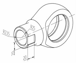
A projection with «3D dimensions»
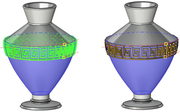
Minimum size of elements. The parameter allows to reduce time of construction and recalculation of projections by omitting small details. In addition such detail exclusion may increase drawing readability in some cases.
The minimum size is set in the current units of model measurement. All bodies with a smaller size won't be shown on the projections.
|
|
|
|
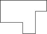
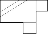
Recalculation time: 0,577 seconds. |
Recalculation time: 0,088 seconds. |
"Basic Parameters" tab

The drop down list found at the bottom of the window defines the type of the projection: “Precise (Image Lines)”, “Vector Picture”, “Rendering”, “Shading”, “Wireframe”.
The following projection parameters are defined here as well:
Perspective projection. Parameter defines type of created projection: parallel or perspective. When the flag is set, perspective projection is created. Dimensions, based on elements of such 2D projection, also drawn according to the perspective parameters.
Consider hidden lines. This parameter defines whether the hidden lines are shown on the projection. This parameter is not available for projections of the following types “Shading”, “Rendering”, and also for sections and cuts.
Show Edges. This parameter controls the view of the edges on the projection (only for projection of the types “Shading”, “Rendering”).
Show Outline. With the help of this parameter, the view of the outline edges of the projected bodies is controlled on the projection (only for projections of the types “Shading”, “Rendering”, “Wireframe”).
Consider transparency. When the flag is set, transparency of objects is considered on the projection. Elements, located behind transparent objects will be shown on projection as well.
The rest of the parameters on this tab reflect the information about the view direction, the scale and relations with other elements. (See the detailed description above.)
"Lines" tab
On the Lines tab you can change image line parameters for particular 3D construction elements, bodies and fragments.

The upper pane displays the list of selected items. You can change lines parameters for the elements.
You can select elements in the Properties window by clicking "..." in the list.
You can select lines parameters for all elements on projection when you select Line styles by default, but if lines parameters are already set for any element in the list, they will not change.
In the center, there is a list of categories of projection lines. If you want to display lines of the category set flag near its name.
Lines Categories
●Basic lines. Allows to set parameters of basic lines.
●Hidden lines. This parameters of this group control the display of invisible lines and parameters of the view on the 2D projection.
●Smooth edges. The projection may or may not display the edges between the smoothly adjoining faces (connected without sharp corners). This group of parameters defines whether to display smooth transitions, and defines the way of displaying graphic lines (type, color, etc.) used for this purpose.
●Axial lines. When projecting surfaces of revolution (cylinder, cone, torus), the axes, or centerlines, can be created automatically. In the case when the body has several surfaces of revolution, the option Unite can be conveniently used for avoiding overlapping of axes.
●The flag “Automatic creation of axial lines” also controls the display of bend axes on the projections of bodies obtained by applying operation SMU: Unbend Bend.
●Threads. When creating 2D projections, the threads existing in the model are recognized automatically. With the option turned on, the lines of the thread notation are created in the cases, when it is viewed on the given projection from the front or side, or when the section plane passes through the thread axis. When creating a dimension on a thread in one of the above representations, the system automatically creates the appropriate notation. The data for the notation is taken from the thread creating operation.
●Bend edges are designed to display lines on the projections of unbent sheet metal parts.

Section lines is used for drawing of visible segments that appear when the projected body intersects planes of stepped sections orthogonal to the direction of the projection.
Hidden smooth edges. Shows smooth lines that are invisible on the projection.
Lines Parameters
Parameters of lines available for changing are displayed in the lower part and depend on the selected category.

You can select several categories at the same time and set common parameters for them.
Any auxiliary type of the projection lines can be assigned Line Type and Thickness, Scale factor, Color.
Use bodies color. With this parameter turned on, the color of all projection lines and section hatches is determined by the color of the operations being projected. All bodies are colored only in the shading mode.

Type. You can select lines type for the selected category from the drop-down list.
Thickness. Specifies lines thickness.
Scale factor. Allows to set scale factor for non-continuous lines.


Color. You can select lines color from the drop-down list or enter number of the color.
Shorten Line parameter is available for smooth lines. If this option is checked, the lines of smooth edges are drawn shortened at both ends.
In the case of the thread, there is an additional parameter, Minimum thread height. It is used to make an exaggerated, to the specified degree, cosmetic thread profile, when the line thickness used in the drawing or the small scale of the projection do not allow to maintain the cosmetic thread legible in its actual size.
Depending on the type of a 2D projection, the dialog of the option ![]() can have additional tabs Gaps, Sections, Coordinate systems. The contents of these tabs duplicates the contents of the similar sections of the properties window when creating/editing 2D projections.
can have additional tabs Gaps, Sections, Coordinate systems. The contents of these tabs duplicates the contents of the similar sections of the properties window when creating/editing 2D projections.
