Editing Techniques


Editing Techniques |
|
Modifying Element Properties Without a Rollback
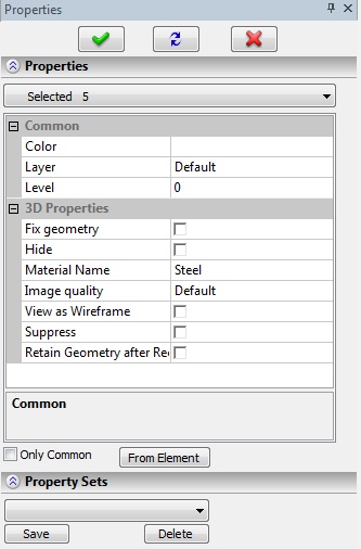
Each system element possesses a certain combination of settings and geometrical parameters. One can view and modify those parameters in the element parameters dialog window. One can call this dialog and modify the values at any time. This is convenient when the full-function editing command is not required, in avoidance of forcing the system to run a potentially time-consuming recalculation up to the edited element.
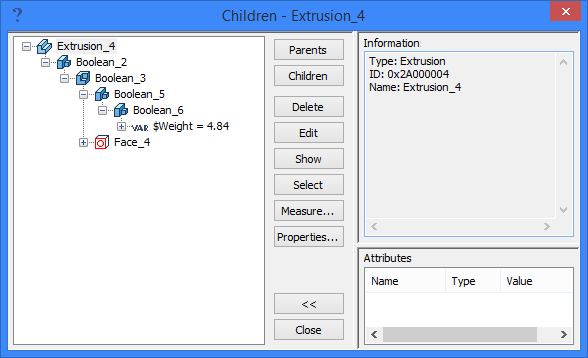
Select the desired element to call its properties dialog. This can be done directly in the “3D Model” window or with the help of the search function. You can select the element by When selecting the element by clicking |
|
"Edit" Command Workflow
Each system element has its own editing command that serves to redefine the setup, modify the source data, etc. Several methods are available to launch the editing commands.
The commands to edit all types of 2D and 3D elements are located in the “Edit” textual menu:
Keyboard |
Textual Menu |
Icon |
<3E..> |
"Edit|Construction|…" |
… |
<3E..> |
"Edit|Operation|…" |
… |
In most cases, the editing command name for a 3D element differs from the respective creation command by just one letter “E” (Edit). Examples: “3N” – “3EN” – these are the commands to construct and edit a 3D node, “3X”– “3EX” – the commands to create and edit an extrusion operation. The icons of the editing commands differ from that of the respective creation commands in the added scissors symbol ![]() .
.
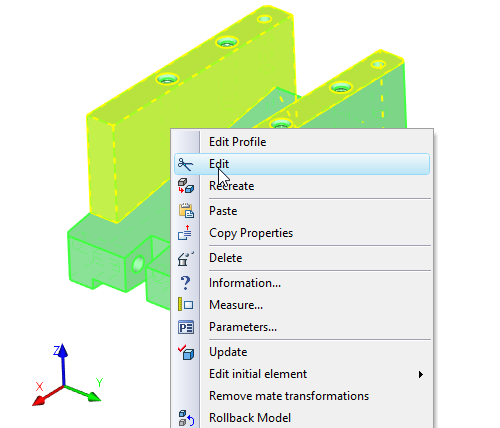
The edit a particular element, you first need to select it, and then lunch the editing command. You can select the element in the 3D window or in the 3D model tree by When the editing command is launched for a particular element, the system appears to be as if in its creation command, with the parameters already defined and geometrical elements selected. The user can proceed using the same methods and techniques as one would use in the element's creation command. Please refer to the dedicated chapters of the documentation for the description of relevant techniques. |
|
If no element was selected at the time of launching the editing command, then you will see the options for selecting an element and general edit-specific actions in the command's automenu:
|
<Esc> |
Cancel selection |
This option clears the selection of the selected objects.
|
<A> |
Select All Elements |
This option serves to select all objects of a particular type present in the model. Invisible objects will be selected if this was allowed by the setting in the command “ST: Set Document Parameters” on the “View” tab.
|
<Z> |
Select element by name |
The list of elements available for selection will appear.
|
<I> |
Select Other Element |
If the first 3D element was selected by the parent 2D element, then using this option will cause subsequent selection of all 3D construction elements of an editable type created based on 2D elements. If an element was selected in the 3D window, then the selection will loop through all similar 3D elements lying on the selection ray. The selection ray is directed perpendicular to the screen plane and goes through the point of the cursor position at the selection instant. Only those elements will be selectable which are located close enough to the point of the cursor. Using this option over causes the sequential selection of all such 3D elements.
|
<P> |
Set entity Parameters |
This option allows to modify parameters of the selected 3D element. When this option is called, the element parameters dialog window appears on the screen. This option is fully analogous to the 3D element parameters editing command accessible from the context menu (by selecting the 3D element in the command-waiting mode).
|
<F4> |
Execute Edit Element Command |
This option launches the element creation command and loads in it all source data attributable to the edited element. After that, the user can make changes to the set of source data using the same techniques as in the element creation command.
|
<R> |
Change Definition |
This option allows to modify the creation method of the selected 3D element. This mode is fully analogous to the 3D element redefinition (recreation) command accessible from the context menu (by selecting the 3D element in the command-waiting mode).
|
<Del> |
Delete Element |
This option's function is fully analogous to the “Delete” command accessible from the context menu (by selecting the 3D element in the command-waiting mode).
|
<M> |
Transformation |
This option calls the “3EG: Transform Element” command for the given 3D element or group of elements.
If several elements of the same type are selected in the editing command using the option ![]() and the <Shift> or <Ctrl> key, then the only options available in the automenu will be the transformation and deletion.
and the <Shift> or <Ctrl> key, then the only options available in the automenu will be the transformation and deletion.
Retain Operation Geometry after Recalculation
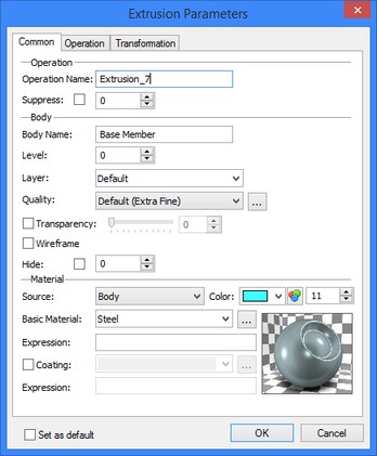
Upon the activation of the editing command, the system rolls back the model to the state in which it was at the time of creating the operation. The elements remaining in the scene are those independent from the edited object. When executing a rollback, a part of the model requires regeneration, therefore the command may take some time to activate.
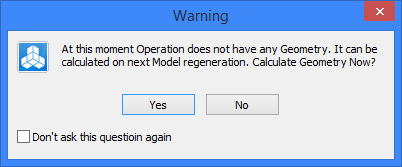
To eliminate this regeneration phase and thus speed up the command activation, you can enable saving the intermediate geometry for a certain operation. This will increase use of computer memory and the model file size to some extent, but will help speed up editing. In fact, saving geometry can be used as a temporary measure while experimenting with model editing. To turn on geometry saving, right-select ![]() the operation (for instance, in the model tree) and choose the “Retain Geometry after Recalculation” item in the context menu. The system will query the user as to when it shall regenerate the model in order to calculate the geometry to be saved - immediately or upon the next recalculation:
the operation (for instance, in the model tree) and choose the “Retain Geometry after Recalculation” item in the context menu. The system will query the user as to when it shall regenerate the model in order to calculate the geometry to be saved - immediately or upon the next recalculation:
When the “Retain Geometry after Recalculation” option is enabled, the operation icon in the model tree is marked with the special symbol ![]() .
.
Element Redefinition
The context menu of any 3D element accessed by ![]() has the “Recreate” command which serves to modify the element's definition method. The system rolls back to the state as before the element creation and launches the element creation command. After that, the user shall create that element anew. This command is typically used instead of simply deleting an element and creating a new one, in case it may be used somewhere else. Therefore, it is important to know that the old element's ID, name and subsequent relations are maintained.
has the “Recreate” command which serves to modify the element's definition method. The system rolls back to the state as before the element creation and launches the element creation command. After that, the user shall create that element anew. This command is typically used instead of simply deleting an element and creating a new one, in case it may be used somewhere else. Therefore, it is important to know that the old element's ID, name and subsequent relations are maintained.
Element Deletion
There are several ways to delete elements from a model. Depending on the case, it may be possible to delete groups of dependent objects or eliminate isolated objects from the model's structure, if possible. The system also allows to automatically trace the objects unused downstream in the model, and delete them.
“Delete” Command (the 3D element deletion command)
The “Delete” command is called from the context menu when an element or a group of elements is selected. The command serves to delete one or several elements (whether 3D or 2D elements). When the selected objects are deleted, their parent elements can also be deleted automatically, upon the condition that the latter are not referenced anywhere else in the 3D model.
When the command is called for the selected 3D element(s), there are two possible scenarios.
If the selected element(s) has neither dependents nor parent elements not referenced anywhere else otherwise, then the deletion will be instant and without any prompts. If the above condition doesn't hold, then, once the command is called, the “Element Deletion” dialog window will appear.
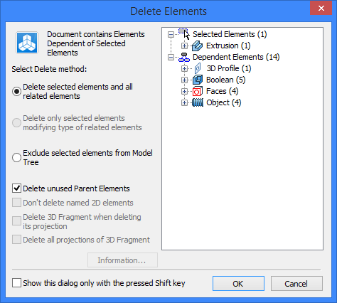
In the left-hand side of the dialog window, you will be able to select one of the possible options of the command's function:
●Delete Selected Elements and all related Elements. If this option is chosen, then the selected elements will be deleted together with all their dependents.
To have the unreferenced parent elements (if any) deleted too, you shall set the flag “Delete unused Parent Elements”. If there are workplanes among such elements, those will be deleted together with their respective pages.
If some of the selected or dependent 2D objects are named, then an additional flag “Don't Delete Named 2D Elements” will be available. With this flag set, the found named 2D objects will be excluded from the deletion list.
When you delete layout elements (schematic images of 3D fragments on the assembly workplanes) the flag Delete 3D fragment when deleting its projection becomes available. You can delete 3D fragment that is linked with the deleted layout element.
When you delete 3D fragment, which has a layout, the flag Delete all projections of 3D fragment becomes available. It allows to delete all its schematic images from all workplanes.
●Delete only selected elements modifying type of related elements. This option is available only when selecting 2D elements (for example, graphic lines on a workplane), which have dependent 2D objects. As a result of choosing this option, only the selected 3D elements will be deleted. As for the children of the deleted elements, the system finds an alternative definition for them.
For example, when LCS linked with a 3D fragment is deleted, the fragment will stay in 3D scene and its position will be fixed. All other links between child and other elements will be broken.
In some cases, geometry or elements of deleted fragments can be left in the scene. For example, if extrusion was created using external profile from the fragment document, the profile and the extrusion will be left in the assembly after fragment deletion.
Another example: when two elements are connected using LCS-connector, the connector will be left in assembly after one of the elements deletion.
Workplanes, nodes and LCS-s remain in a document if their parent element was deleted. Their location is kept according to all transformations. If such object is created using several other objects, and one of the objects is deleted, the link with all other parent objects will break too.
The only exclusion are 2D nodes that define workplane borders. The workplane can’t break links with them.
●Exclude selected elements from Model Tree (by reassigning the references of dependent elements to other elements). When this method is used, the system attempts to switch the references of the dependent elements to other model objects. When an operation is deleted, the references of its dependent 3D elements are reassigned to the operation that stands before the deleted one in the 3D model tree. This option is available only in the case when the deleted 3D element has both a parent operation and a dependent 3D element.
The list of the elements to be deleted is displayed in the right-hand side of the dialog window. The elements are sorted by types and are placed into the appropriate folders. To view the information on the elements selected for deletion, you can click the [Info…] button.
If the option “Only show this dialog when the Shift key is down” is flagged, then the “Element Deletion” dialog will not be displayed upon subsequent calls to the command. To have it display when the command is called, you will have to additionally hold <Shift>. The command will be working in this way until the user changes this setting or until the end of the current T-FLEX CAD work session.
“Delete Body” Command
When a Body is selected (which can be done in the 3D model tree) then instead of the “Delete” command the context menu will provide the command “Delete Body”. This command will delete from the 3D model all the operations which are part of this Body's creation history. Besides that, the command allows to delete the parent elements used in this Body's operations.
After calling the “Delete Body” command, the following dialog window is displayed.
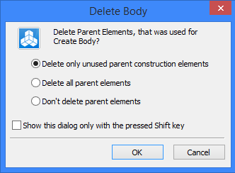
You need to select one of the following actions regarding the deletion of auxiliary elements:
●Delete only unused parent construction elements. As the Body is deleted, so are the construction entities and workplanes, together with their pages, if those are not referenced by other elements.
●Delete All Parent Elements. The selected Body is deleted together with all elements used in the body's operations (construction entities, variables, etc.), which are not referenced by the model's other Bodies.
●Don't delete parent elements. Only the operations that form the selected Body will be deleted.
The flag “Only show this dialog when the Shift key is down” has the function similar to the same-name flag of the 3D element deletion command.
“Purge” Command
The command “Edit|Purge” serves to delete all 2D or 3D construction elements that were used neither for creating graphic lines of the 2D drawing nor for operations.
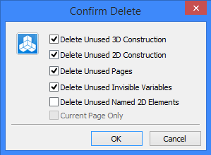
After calling the command, the “Purge” dialog window is displayed. In it, you can set the following flags:
●Delete Unused 3D Construction. All unused 3D construction elements will be deleted. 'Unused' are considered the 3D construction elements that are not referenced by a single operation.
●Delete Unused 2D Construction. All unused 2D construction elements will be deleted, which are those not involved in creating 2D graphic lines, hatches, dimensions and other drawing elements. The named 2D constructions, that is the 2D construction elements assigned individual names are not deleted by default. To have them deleted, you would need to turn on an additional flag “Delete Unused Named 2D Elements”.
●Delete Unused Invisible Variables. All invisible system variables (do not confuse with the “Hidden” document variables displayed in the variable editor) that are not used in the model will be deleted.
●Delete Unused Pages. All empty pages in the current document will be deleted.
The unused 2D pages also include the pages of workplanes created automatically by the “Draw On Face” command if the user didn't use them to create anything. Such pages are deleted together with the projections of source faces which were automatically created on those pages.
●Delete Unused 3D IDentifiers. As the unused 3D IDs are deleted, the 3D model size gets reduced. As a result, the undo stack of the “UN: Undo Changes” command also gets cleared.
When 2D elements are deleted on a page of a 2D drawing or on the active workplane, the following additional flags are available in the command's dialog:
●Delete Unused Named 2D Elements. When this flag is set and the unused 2D constructions are deleted, the named 2D construction elements will be deleted too. In addition, this flag allows deleting the workplanes created on faces, if the projections on those workplanes include named graphic lines.
●Current Page Only. When this flag is set, the unused 2D constructions will be deleted only on the current page of the 2D drawing or on the active workplane.
Source Geometry Editing Command
This command allows to quickly select for editing the geometrical elements used for creating the selected 3D element. The list includes the 2D objects (hatches, 2D paths, 2D nodes, etc.), which were used for creating the selected 3D element and its parent elements. If a 3D element, for example, a 3D profile, was created based on a set of graphic lines on a workplane, then the “geometry” list also includes the workplane itself.
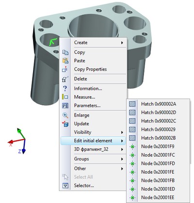
When you select a 2D element in the list of the source geometry, the appropriate drawing page opens and the mode of drawing on the workplane activates; at the same time, the editing command for the selected element is launched. Therefore, this command can be conveniently used to quickly go to the page of the source workplane of a given 3D object.
Command Edit Profile is available in context menu of operations, created from 3D profiles (for example extrusion and rotation), and workplanes, on which 3D profiles were created. The command activates the workplane on which the source 3D profile is located.
Handling the Drawing Elements while Editing
When modifying a 3D model, one may often have to deal with drawing elements, since those may be used as references for constructing base 3D model elements (3D profiles, 3D paths, 3D nodes, etc.). The user may proceed with the same editing techniques for 2D elements as one uses when working with a conventional drawing. To modify the shape of a 3D element constructed on the basis of 2D elements, you need to appropriately redefine the source 2D elements. Some of them, for example, hatches directly related with 3D profiles, cannot be deleted and built anew, unless the entire model tree branch is to be deleted together with the children of that hatch. In order to redefine such hatches, one should use the function of editing hatch contours. Otherwise, the model's structural integrity can be broken. If a 3D profile was created based on a set of graphic lines on a workplane, then those lines can be freely modified, including deletion and subsequent new creation. When the session of drawing on the active workplane is over or when the system undergoes the next calculation, the 3D profile will be rebuilt according to the modifications to the graphic lines.
If a certain 2D construction element needs to be modified but cannot be deleted, then you can rebuild it by using another creation method for it in the editing command. The option to rebuild 2D construction elements is available in the automenu of the construction lines editing command.
Sometimes it is helpful to use the command “RL: Replace Element”. It allows to transfer all relations with parents and children from one 2D construction element to another one, and then delete the original element. In this case, the other construction element may use a different construction method and maintain its own relations or dependent elements.
Avoiding Recursion
When creating long chains of element dependencies, the user may run into an attempt of creating a recursive dependency, that is, a dependency of a certain element on itself. In most cases, the system automatically checks the created relations and does not allow saving the changes that cause a recursion. Yet in isolated cases a recursion may occur. Such dependences are seen most of the times in complex chains of relations like "3D elements - 2D elements - 3D - 2D and so on". One danger of the situation for the user is that the one may save the file with a recursion and not be able to undo the erroneous actions when opening this file later. In such a case, it won't be possible to normally work with the file in which the system detects a recursion, up until it is rectified.
In such a situation, the elements shall be edited in a special way. As was already mentioned, upon an attempt to make any changes, the system will run a check for invalid relations in the modified chain of dependent elements. If such invalid relations are found, the system will disallow the changes. This creates certain complications for the user in one's attempts to delete or edit elements.
The user's goal shall be detecting a recursive relation and breaking the chain of dependences at any suitable point, all in one editing step. It is often enough to change the definition method of a certain element in the recursive chain. This could be either a 2D or a 3D element. You can redefine the element by changing its definition method - for example, define its position in absolute coordinates or relate it with some other independent elements.
Such elements can be identified with the help of the diagnostics window - the names of the elements are indicated in the recursion warning line. Next, you need to investigate the dependencies between the elements - you can call the “Info” window for that purpose. After identifying the causes of the recursion, one can proceed to editing. Once corrections are made, run the model recalculation to check and make sure there are no new warnings.
Techniques of Simplifying the Model Structure and its Display in the 3D Window
T-FLEX CAD system provides means for speeding up primary work processes - this is achieved by freeing additional computer resources when some secondary processes and model details are temporarily dropped.
1.Display simplification:
●the use of the wireframe display mode in most cases helps the system faster recalculate the objects in the scene and speeds up the scene spinning and object selection;
●The image quality deterioration affects the display of 3D objects in the scene. The objects appear coarser but are drawn faster. The image quality can be controlled in the “ST: Set Document Parameters” command, on the “3D” tab;
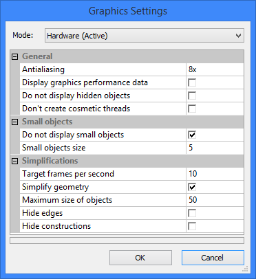
●The 3D model display simplification settings help when spinning the 3D scene densely populated with model elements. Those are system settings that are defined in the command “SO: Set System Options”, on the tab “3D”. To call the setup dialog, click the button [Graphics Settings].
●Any element in the 3D scene can be made invisible. Reducing the number of elements in the scene helps speed up the display. An element can be hidden by means of changing the level settings, the layer, or by using the “Hide” command in the drop-down “Visibility” submenu of the context menu of the element right-selected with ![]() .
.
2.Element Suppression. By suppressing individual operations, the user not just hides them from the 3D scene, but also excludes them from the regeneration process. This also helps reduce the total model regeneration time. An operation can be suppressed by calling the “Suppress” command from the context menu or by setting the element suppression in the parameters dialog window on the “General” tab.
3.Set of options to assist in handling a large assembly model. These options are provided in the command “ST: Set Document Parameters”, on the tab “Large Assembly Management”.