Sections


Sections |
|
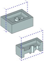
The 3D section is an auxiliary 3D construction element in T-FLEX CAD. It is used as a secting object when creating 2D projections (for obtaining local area views and sections) in the "Cut by section" operation. The 3D section can be used when viewing objects of the 3D scene, helping quickly examine the inner model structure without changing it.
The section is displayed in the 3D scene by dotted lines indicating the boundaries of the 3D section. The arrows on the image of a 3D section indicate the view direction. The view direction of the 3D section defines the part of the model that would remain as a result of applying the section to a 2D projection, a model in the 3D scene or when cutting by section.
A 3D section can be defined by one of the following methods:
●With an octant (trihedral angle);
●With a planar angle (dihedral angle);
●On the basis of a plane;
●With a parallelepiped
●As a result of extrusion of the specified curve in a certain direction. The initial curve can be specified:
●based on a 3D view;
●based on 2D constructions on the workplane;
●based on a 2D projection.
3D section by octant and planar angle
To create a 3D section with an octant and a planar angle, it is sufficient to indicate the location of the secant trihedral or dihedral angle in the space. To specify the location of the section, use the special manipulator in the form of the LCS to which the view of the secant angle is attached. Position of the secant angle can be snapped to points of the 3D model and also to LCS.
The created 3D section is displayed in the 3D scene in the form of a dashed rectangle coinciding with the X-Y plane of the manipulator of the section. The boundaries of the rectangular section are imaginary and only used to display the section in the 3D scene. The direction of the sight is parallel to the Z-axis of the manipulator of the section and has an opposite direction.
3D section based on a plane
When creating a 3D section of the given type, the location of the secant plane is specified with the help of the special manipulator. It constitutes the LCS to which the “draft” of the secant plane is attached. The location of the secant plane can be specified and controlled with the help of the manipulator and commands of its context menu. Position of the secant plane can be snapped to points of 3D model.
The secant plane can also be specified by simply indicating the 3D object that defines the required geometric plane (planar face, planar edge, workplane, etc.).
The view direction of the 3D section is set by the system arbitrarily, and the user can change it, if necessary.
The boundaries of the 3D section in the 3D window are purely imaginary and are used solely to display the section in the 3D scene. The model is slashed by such section throughout the entire range of the section plane. Direction of the sight of the 3D section is determined by the system arbitrarily but the user has always a possibility to modify it.
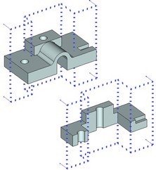
3D section based on a parallelepiped
To create a 3D section with a parallelepiped it is sufficient to indicate dimensions and location of the secant parallelepiped. Note that when applying the section of the given type everything that is situated outside the parallelepiped will be cut off.
To specify location of the section, the special draggers in the form of LCS are used to which two opposite vertices of the parallelepiped are snapped. Location of the secant parallelepiped can be snapped to points of the 3D model, and also to LCS.
Created 3D section is displayed in 3D scene as a dotted parallelepiped.
3D section as a result of extrusion of specified curve
3D section can also be specified as a list body obtained as a result of extrusion of the specified curve (line of the section) in a certain direction. To do so, it is possible to use one of the three variants of creation of 3D section:
●based on 3D view;
●based on 2D constructions on a workplane;
●based on 2D projection.
These approaches differ in the way of defining the source curve of a 3D section and the direction of its extrusion. The view direction of a 3D section is arbitrarily defined by the system, regardless of the creation technique, however, the user can always flip it.
The boundaries of such 3D sections are imaginary only in the direction of extrusion of the initial curve. The extents of the section in the other direction are precisely determined by the boundaries of the source curve. Therefore, when creating a 3D section, make sure that the base curve fully intersects the 3D model. Otherwise, only a portion of the model will be sected that is intersected by the base curve of the 3D section.
The 3D sections, created based on 2D projection and 2D constructions on a workplane, by default are not displayed in the 3D scene. To make such section appear in the 3D window, set the flag “Show Image in 3D View” in the section parameters.
3D Section Based on 3D View
The curve that guides creation of a 3D section is specified by a set of 3D points (3D nodes or body vertices). The selected 3D points are joined by straight segments. The 3D section is constructed by extruding the resulting polyline in the normal direction to the screen (at the time of selecting the first point).
Before creating a 3D section, you need to a pointing and the 3D scene to make it perpendicular to the desired direction of the section creation. This can be done, for example, by using the command “3VP: Set View Parameters”, selecting the desired view position with its help. Or, if the 3D section is to be made perpendicular to some face or flat edge of the model, you can use the command “3VN: Rotate Normal to Selected Element”.
A section, created based on 3D view, is displayed only in the 3D window.
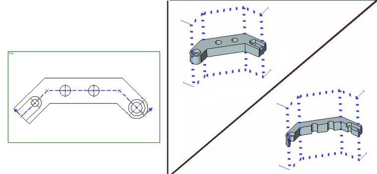
3D Section Based on 2D constructions on a Workplane
The base curve of a 3D section is defined by 2D elements lying on workplane:
-a set of 2D nodes (two and more nodes);
-a 2D path;
-a view notation (2D section), created by the command “SE: Create Section”.
The resulting flat curve as extruded perpendicular to the workplane, that is referenced by the source 2D elements.
When using 2D nodes, the curve is created as a polyline (the specified nodes are connected by straight segments). The 3D section will be composed of planar segments in this case.
If a 2D path is selected, the base curve of a 3D section will exactly follow the path shape. The 2D path can be of arbitrary shape. Therefore, 2D paths allow creating 3D sections, containing segments of selected circle or spline surfaces.
The 3D sections, created based on 2D nodes and 2D paths, are displayed in the 2D view window by a dotted line with the arrows at the ends, indicating the view direction of the section.
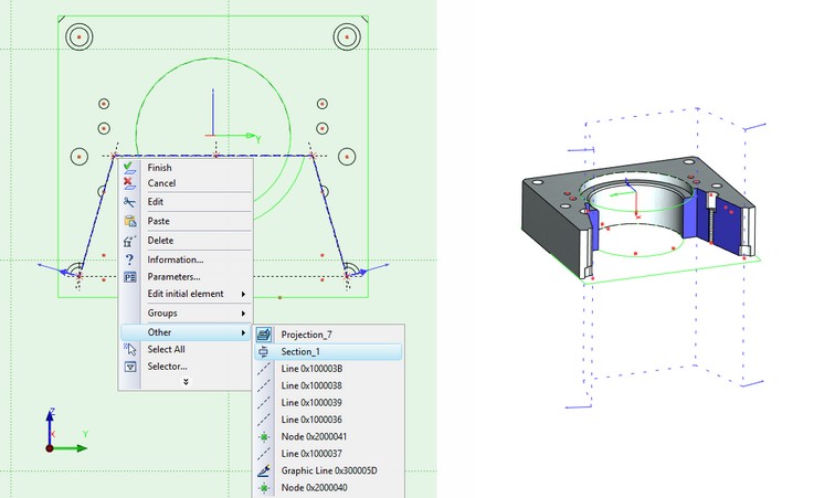
A view notation is commonly used, when the 3D section is crteated based on existing 2D drawing. The base curve of the 3D section will repeat the shape of the 2D section, created in the command "SE: Create Section". Such 3D section is not displayed in the 2D window. You can find out about its presence in the drawing from the 3D model tree or from the context menu for the 2D section.
There are two additional options for this method of creating a section in an automenu.
|
<O> |
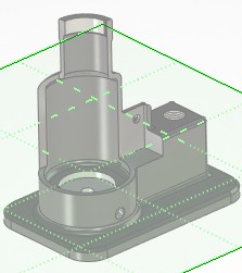
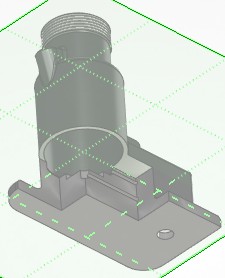
One-sided section |
|
<D> |
Switch direction of one-sided section |
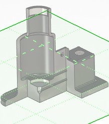
When the One-sided section option is activated, the part of the model that is below (or above) the Workplane onto which the element (s) was selected, the specifying section will not be cut off. The option Switch direction of one-sided section changes the part of the model that is not cut off: either under the Workplane or above it.
|
|
|
Without options |
|
|
Creation of 3D section based on 2D projection
This way of the section creation is almost exactly identical to creating the section based on workplane. The section is constructed perpendicular to the direction of projecting the source 2D projection. The base curve of a 3D section is defined by 2D elements one the projection: a set of 2D nodes, 2D path, view notation.
Such 3D section can be created automatically in the 2D projection creation command when constructing a local view or section based on a 2D view notation.
Selection of Objects of the Section
When creating a section, it is possible to specify a set of objects of the section. The Bodies, operations, welded joints can be selected as such objects of the section. The selected set of objects can be used in one of the three modes:
●section is applied only to the selected objects;
●section is applied to all elements of the model except the selected ones;
●section is applied to all elements of the model (the specified set of objects is removed).
Applying section to 3D model
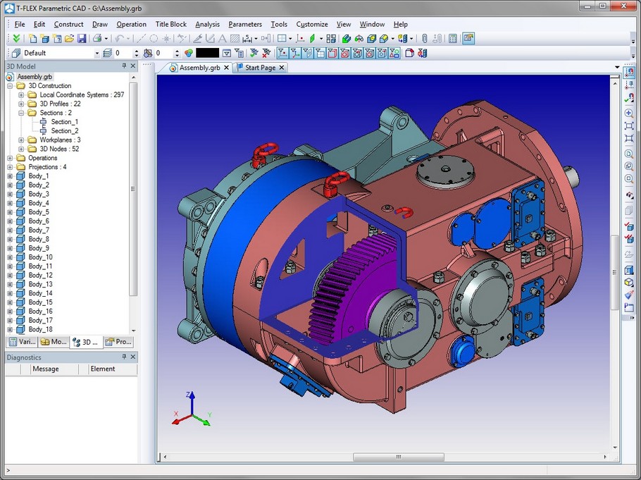
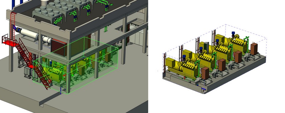
A 3D section can be used for viewing a 3D model. This helps quickly examine the inner structure of the model and evaluate the shape of the model of the setting with this 3D section.
When viewing a model with the help of 3D section, the body is "slashed" by the 3D section into two parts. The 3D scene displays only the portion have the disappointed up by the view direction arrows of the 3D section. In this way, no actual separation is performed, the model itself is left unchanged, what is changed is just the way of its rendering in the 3D scene.
Note that when a section is applied in the 3D scene, you can neither select edges, faces or vertices nor save the document. To do any of these actions, you need to cancel the section.
To apply a section to the model, call the command "View|Apply Section". A dialog box will be displayed, listing all sections existing in the document. Select the desired section in the list (it will become highlighted both in the 2D window and in the 3D scene) and press the button [OK] in this dialog. The section will be applied to the model.
There is another way of calling this command. In the command waiting mode, right click ![]() in the 3D view window. In the coming up context menu, select the command "Apply Section…". As a result, the described dialog box will appear.
in the 3D view window. In the coming up context menu, select the command "Apply Section…". As a result, the described dialog box will appear.
A section can also be applied to the model from the context menu of the particular 3D section (by right clicking ![]() ). In this case, you do not have to select the section. The section will be applied to the model, whose context menu was called.
). In this case, you do not have to select the section. The section will be applied to the model, whose context menu was called.
Canceling section is done by the respective command that can be launched from the context menu of the 3D section (by selecting it in the 3D window or in the 3D model tree).
Geometric section
Starting with T-FLEX CAD 12 and above, two methods of section creation are used when creating 3D sections.
The basic method – “graphic” section – is used by default when creating sections by the octant, planar dihedral node and on the basis of a plane. Such a section, after it has been applied, allows us to work with 3D model without restrictions by selecting edges, faces and vertices of a 3D model for performing any constructions. But when applying this section the system is not able to render outline edges of the section. Moreover, the “graphic” section has one important restriction – it is not possible to apply simultaneously more than one graphic section to the body in 3D scene.
When creating the sections on the basis of 3D view, of 2D constructions on the workplane and on the basis of a 2D projection, the old mechanism of section creation – “geometric” section – is used. When using this method (used in T-FLEX CAD of version 11 and lower) application of the section excludes selection of edges, faces and vertices and also saving the document. As long as the section is applied, the further editing of the dissected body is excluded. But when using this mechanism the outline edges of the body’s section – that is, the lines of intersection of the section and the body being dissected – are displayed, and several “geometric” sections can be applied simultaneously to the same body in 3D scene.
If desired, the user can also apply the old mechanism of section creation – “geometric” section – to the sections by octant, planar dihedral node and on the basis of a plane. The corresponding flag is available in the properties window of the 3D section creation/editing command.
Old types of sections (on the basis of 3D view, of 2D constructions on the workplane and on the basis of a 2D projection) can be created only as “geometric”.
Creating section
To create a section, use the command "3SE: Construct Section":
Icon |
Ribbon |
|---|---|
|
3D Model → Construct → Section |
Keyboard |
Textual Menu |
<3SE> |
Construct > Section |
Upon calling the command, the automenu will offer both the general system options and the options for selecting a method of creating the 3D section:
![]() <W> Construct Section using Workplane
<W> Construct Section using Workplane
![]() <V> Construct Section using 2D Projection
<V> Construct Section using 2D Projection
![]() <R> Construct Section using 3D View
<R> Construct Section using 3D View
![]() <L> Create Section by Plane
<L> Create Section by Plane
![]() <O> Create Section by Octant
<O> Create Section by Octant
![]() <A> Create Section by Plane Angle
<A> Create Section by Plane Angle
![]() <B> Select Bodies for Section
<B> Select Bodies for Section
![]() <E> Construct Section by Parallelepiped
<E> Construct Section by Parallelepiped
Creation of 3D Section by Octant/Planar Angle
After selection of the ![]() or
or ![]() options, in the 3D scene a preliminary image of the secant angle with the manipulator in the form of the LCS at the base appears. Location of the secant angle is defined by translation/rotation of the manipulator.
options, in the 3D scene a preliminary image of the secant angle with the manipulator in the form of the LCS at the base appears. Location of the secant angle is defined by translation/rotation of the manipulator.
The manipulator constitutes a view of the coordinate system. The coordinate axes are connected with each other by colored arcs and rectangular “areas”, the center of the manipulator is marked with a sphere. Different parts of the manipulator are the active elements intended for specification of the following transformations:
●the axes of the manipulator are intended for specification of translations along individual axes;
●rectangular “areas” connecting axes of the manipulator in a pairwise manner are intended for translations across the XY, XZ or YZ planes;
●arcs of the manipulator are intended for specifying rotations;
●the center of the manipulator is used for an arbitrary translation (without fixing to axes).
When pointing at the coordinate axis, the user can proceed to specifying a translation along the selected axis. When pointing at the arc, the system prompts the user to specify a rotation in the corresponding plane. In the latter case, in addition to that, the axis of the manipulator closest to the cursor is selected so that the user could specify the rotation by directing the selected axis at the specific element of the model. When clicking the center of the manipulator, the manipulator itself and the secant angle that is linked to it start to dynamically move following the cursor.
To specify a transformation with the help of the manipulator, the user must choose the active element of the manipulator by pressing ![]() . Next, without releasing the pressed button, the user can move the cursor. Transformation will be specified when the mouse button is released. It is also possible, after selection of the manipulator, release the mouse button, move the cursor and select a new element (specify a location in the space), to fix the transformation, by clicking
. Next, without releasing the pressed button, the user can move the cursor. Transformation will be specified when the mouse button is released. It is also possible, after selection of the manipulator, release the mouse button, move the cursor and select a new element (specify a location in the space), to fix the transformation, by clicking ![]() again.
again.
To snap the secant angle to LCS the following option of the automenu is used:
![]() <F> Select coordinate system
<F> Select coordinate system
After invoking the option it is required to indicate the desired LCS.
The context menus of the elements of the manipulator offer additional capabilities of defining orientation of the secant angle. For example, with their help it is possible to direct the selected axis of the manipulator at a 3D point or translate the axis up to the specified surface. The option that is common to all menus – “Settings…” – invokes the dialog for specifying the step of the translation of the manipulator.
After specifying the required location of the secant angle in the space, it is required to confirm its creation with the help of ![]() in the properties window or in the automenu.
in the properties window or in the automenu.
Creating a 3D section based on a plane
After selecting the option ![]() , the following two options will appear in the automenu:
, the following two options will appear in the automenu:
![]() <L> Create Plane
<L> Create Plane
![]() <Tab> Switch view direction
<Tab> Switch view direction
![]() <F> Select LCS
<F> Select LCS
![]() <B> Select Bodies for Section
<B> Select Bodies for Section
The green plane – a «workpiece» of the secant plane, and the special manipulator in the form of the LCS for controlling the location of the plane appear in the 3D scene. With the help of the manipulator and commands of its context menu, it is possible to specify and control the location of the secant plane.
To fix the secant plane to an already existing 3D element (a face, a plane, etc.), it is possible to use the ![]() option. The drop-down list of the option
option. The drop-down list of the option ![]() contains the filters to select 3D objects that define a plane. It is also possible to fix the plane to different 3D points when moving the dragger by using double pressing of the mouse.
contains the filters to select 3D objects that define a plane. It is also possible to fix the plane to different 3D points when moving the dragger by using double pressing of the mouse.
The option ![]() toggles the view direction of the 3D section being created. Once the plane and the view direction of the section are selected, confirm the section creation by clicking
toggles the view direction of the 3D section being created. Once the plane and the view direction of the section are selected, confirm the section creation by clicking ![]() in the properties window or in the automenu.
in the properties window or in the automenu.
Creation of 3D Section with Parallelepiped
After selection of the ![]() option, will appear a preview image of the secant parallelepiped with two draggers in the form of LCS in the lying opposite vertices. To specify the required location and size of the parallelepiped it is required to translate/rotate the draggers.
option, will appear a preview image of the secant parallelepiped with two draggers in the form of LCS in the lying opposite vertices. To specify the required location and size of the parallelepiped it is required to translate/rotate the draggers.
The master vertices of the parallelepiped can be snapped to different 3D points when moving the draggers by double pressing of ![]() .
.
To specify the initial coordinate system, one of the vertices of the parallelepiped can be snapped to LCS with the help of the option:
![]() <F> Select coordinate system
<F> Select coordinate system
The dragger of the vertex will be superposed with the selected LCS.
Coordinates of the second vertex of the parallelepiped (associated with a second dragger) are measured with respect to the coordinate system.
Creating section based on 3D view
Upon selecting the option ![]() , the automenu will provide the additional options for selecting 3D points, the source curve of the section being created, and for switching the view direction of the section.
, the automenu will provide the additional options for selecting 3D points, the source curve of the section being created, and for switching the view direction of the section.
3D points can be selected by the following options:
![]() <N> Select 3D node
<N> Select 3D node
![]() <V> Select Vertex
<V> Select Vertex
You can select as many 3D points as necessary using these options. If some point was minced when specifying the points, cancel the selection and define the points anew. To cancel the selection of a set of points, use the option:
![]() <K> Eliminate all Section Nodes
<K> Eliminate all Section Nodes
To flip the section view direction, offered by the system, use the option:
![]() <Tab> Switch view direction
<Tab> Switch view direction
Upon selecting 3D points and view direction of the section, confirm its creation by the option ![]() in the properties window or in the automenu.
in the properties window or in the automenu.
Creation of sections based on 2D constructions on a workplane
A section can be constructed in this way either in the 2D window (on the page of the 2D drawing related to the workplane), or in the 3D window on the activated workplane.
Upon activating this mode by the option ![]() , select 2D elements defining the source curve for the section. This can be done by the following automenu options:
, select 2D elements defining the source curve for the section. This can be done by the following automenu options:
![]() <N> Select Next Section Node
<N> Select Next Section Node
![]() <C> Select 2D Path
<C> Select 2D Path
![]() <M> Create 2D Section for creating 3D Section
<M> Create 2D Section for creating 3D Section
The workplane used as the base for the 3D section construction, is automatically selected by the system. In the cases, when another workplane can be selected (for example, if several workplanes are located on the given 2D page), the automenu will provide the option for changing the workplane:
![]() <W> Select Other Workplane
<W> Select Other Workplane
To flip the view direction of the section, as in the previous case, use the option:
![]() <Tab> Switch view direction
<Tab> Switch view direction
Upon selecting the source curve, the workplane and view direction of the section, confirm its creation by the option ![]() in the properties window or in the automenu.
in the properties window or in the automenu.
Creation of section based on 2D projection
Creation of a 3D section in this way is done by the option ![]() . Creating such section is exactly identical to the previous method (creating a 3D section based on workplane).
. Creating such section is exactly identical to the previous method (creating a 3D section based on workplane).
The 3D section based on 2D projection can be created by the system automatically (without calling the command "3SE: Construct Section") within the command of creating the 2D projection when constructing a local area view or section based on a 2D view notation.
Selection of Objects of Section
The set of objects of a section is specified with the help of the properties window.
The list of objects can be specified both directly when entering the “3SE: Construct section” command (before selection of the section creation method), and during the stage of creation of the 3D section of any type. In the former case, the specified set of objects is automatically applied to all sections that are created during the current session of work with the command. In the latter case, the specified set of objects acts only for the specific section.
Place the cursor into the “…” line and press
The drop-down menu of this option contains the list of filters of the objects being selected (Body/operation/welded joint).
Objects can be selected in the 3D window or in the tree of the 3D model. |
|
|||
The way of interpreting the specified set of objects (Apply to all elements; Apply only to selected elements; Apply to all elements except selected ones) is set up with the help of the drop-down list “Apply to”. |
|
Defining parameters of 3D section
Defining parameters of a section is done by the parameters dialog (the option ![]() ).
).
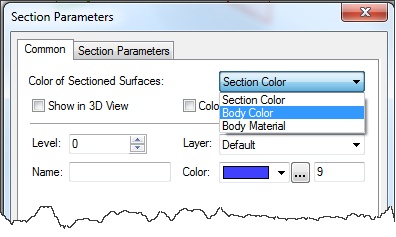
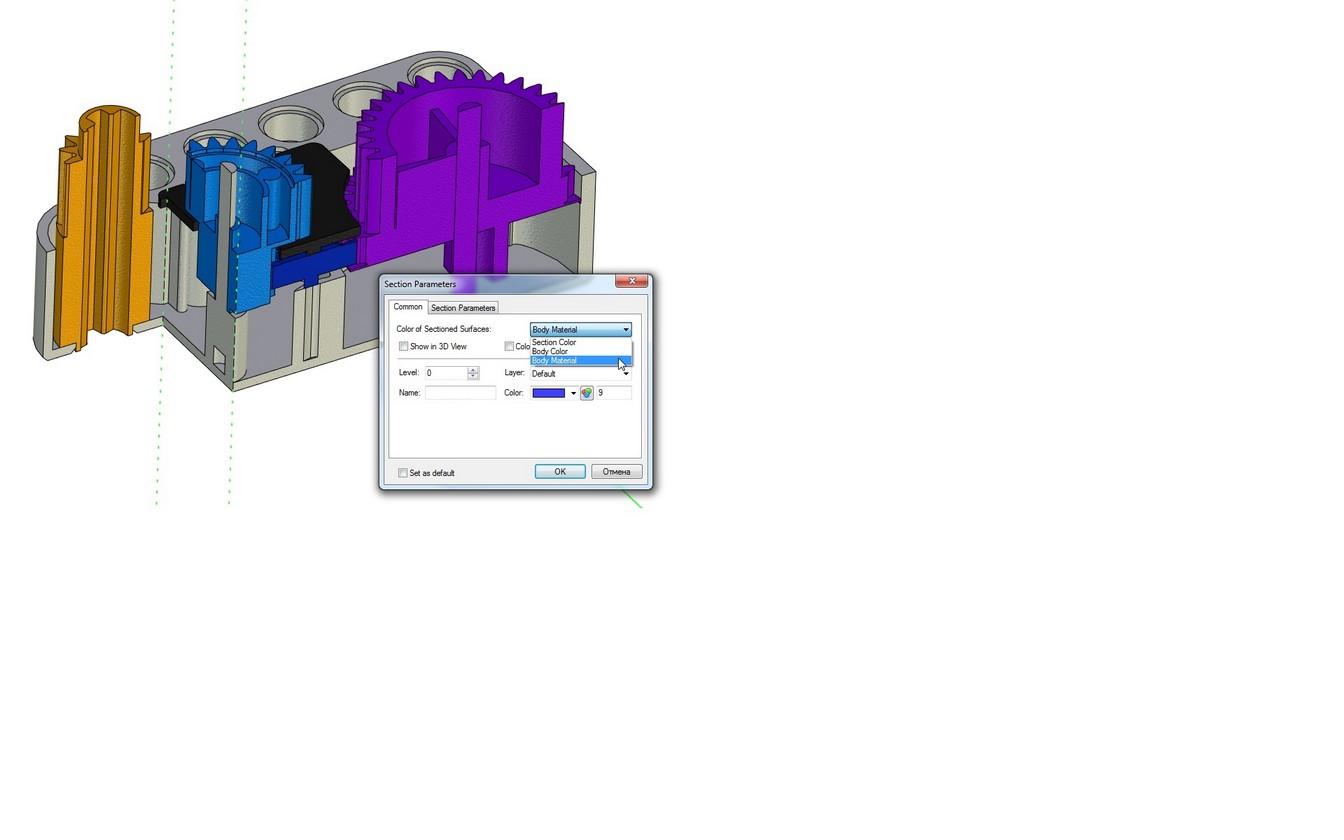
Body Color. When this flag is turned on, then the surface generated as a result of applying the section will be displayed in the same color, as the model. When the flag is cleared, color is used specified in this dialog.
Show on 3D View. Defines the display of the section plane in the 3D view.
Section Color of the section. This color is used for drawing the section in the 2D and 3D windows. Additionally, this color is used for painting surfaces resulting from slashing the model, when the "Color from solids" flag cleared.
Body material. Section is displayed using the material of the body according to material’s texture, color and other characteristics.
It is possible to get different colors when sectioning multicolor assemblies. If parameter value is set to "Body Material", the visual properties of material including texture will be used.