Project Elements


Project Elements |
|
The Project Elements command becomes available in the workplane.
Icon |
Ribbon |
|---|---|
|
Workplane → Modes → Project Elements |
The command allows projecting 3D scene elements onto the active workplane: Nodes, Patches, Profiles, Vertices, Edges, Faces, the intersection with the active workplane of these elements, surfaces outlains. Lines or points obtained when projecting can be used to create 3D elements, or to position other lines based on which 3D elements will be created. In the latter case, the line obtained when projecting should be made Auxiliary.
All created projection lines and points are associatively rearranged as the projected 3D elements change.
You need to start drawing on any workplane or on a face (when drawing on a face, a workplane is created automatically) in order for the command of projecting elements to become available in the Ribbon. In other words, you should make an existing or new workplane active.
|
|
In the mode of drawing on the active workplane, the group “Modes” appears in the Ribbon. The Project Elements command is available in the group.

The Project Elements command has three basic ways to create projected lines and points based on 3D elements. Each option for creating projection lines and points has its own icon in the dialog.
|
Projection to Workplane |
|
Intersections with Workplane |
|
Projection of Elements Outline to Workplane |
To complete the command and construction lines according to the specified parameters, you need to press the automenu command ![]() or <Ctrl + Enter>.
or <Ctrl + Enter>.
Often when working with the command, it is convenient to change the view on the active workplane. To freely rotate the 3D scene in the active workplane mode, click the ![]() Rotate Scene icon. The icon is located on the right on the View Toolbar by default. If the scene rotation mode is active, the created constructions on the workplane will be inaccessible for editing properties. To turn off the Rotate Scene mode, click the icon again. If any command for creation of 2D elements was selected, the Rotate Scene mode will automatically turn off.
Rotate Scene icon. The icon is located on the right on the View Toolbar by default. If the scene rotation mode is active, the created constructions on the workplane will be inaccessible for editing properties. To turn off the Rotate Scene mode, click the icon again. If any command for creation of 2D elements was selected, the Rotate Scene mode will automatically turn off.
In the mode of drawing on the active workplane, other view control commands are available (which are also on the View Toolbar): |
|
In the Ribbon, three more view control icons are available in the Modes group.
The first icon The second icon |
|

Pressing the icon ![]() again restores the initial display of the 3D model.
again restores the initial display of the 3D model.
The third icon |
|
Projection to Workplane
You can project a Face, Edge, Vertex, Profile, Patch, 3D Node on the plane while in the mode of drawing on the active workplane. To do this, call the Project Elements command in the Ribbon and select the Projection to Workplane option (active by default).
The filters toolbar displays a list of all possible 3D elements for projecting in this way by default.
![]()
|
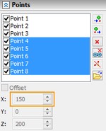
You should select the projection option in the command parameters (in this case, the first one). The active workplane and elements are automatically selected. The list of selected items can be completely cleared using the icon The following two options are also available: Create Auxiliary Lines and Project Direction. In the first option is enabled, all lines created using projecting will be auxiliary. |
|
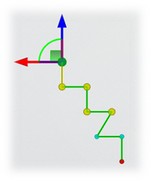
If the second option is disabled, then the projection is performed along the normal to the workplane. If the option is enabled, then it is necessary to specify the direction of projecting the element on the workplane. The direction may specified by an edge, a normal to a face or an axis of a cylindrical surface. For example, you can project the edges of the nozzle flange in the direction of its axis. Then in the Project Direction option field you need to select a cylindrical face: the axis of the cylindrical face will set the direction of projection. |


As a result, projection lines will be created on the active workplane. In this case, the auxiliary lines are created as the appropriate option was enabled.
|
|
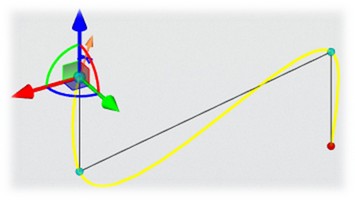
Normal projection (without using Project Direction option) |
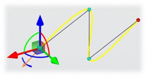
Projection by Direction (using the Project Direction option) |
Intersections with Workplane
Using this option of the Project Elements command, elements that are formed when the active workplane intersects edges, edges, profiles, paths or other workplanes and work surfaces can be projected on the active workplane. The specified list of elements corresponds to the filter option.
![]()
When the active workplane intersects edges, profiles, or other workplanes and work surfaces, they are projected as lines. When the active workplane intersects edges or paths, they are projected as points.
For example, you can get the line of intersection of the nozzle faces with the workplane passing through the body of the nozzle. To do this, you need to make the workplane active, select the Project Elements command in the Ribbon and specify the Intersections with Workplane option. Next you need to select the faces of the nozzle. If you select the outer faces - the outer contour of the nozzle section by the workplane is created.
|
|
If you select both outer and inner faces, the complete contour of the nozzle section by the workplane is created.
|
|
Several selected faces are specified twice in the list of elements, as it can be seen from the example. For example, "Face_28".
The intersection of the element "Face_28" with the workplane forms two edges, and, therefore, you can create two projection lines.
|
|
|
|
If you need to project only one intersection line, you can disable the All Components option. Then only the intersection that is closer to the cursor at the moment of selecting the face will be projected. Another way is to remove an extra element from the list using the icon ![]() .
.
If you select the edges of the intersection of the nozzle faces then the result of the command will be points projections.
|
|
As can be seen from the example, two selected edges create projections of four points, since each edge has two intersections with the active workplane. If you need only one intersection point of several, then you need to act by analogy with the previous example: Do not use the All Components option or remove items from the list using ![]() .
.
Projection of Elements Outline to Workplane
With this option, you can project an outline of a body along the normal on the active workplane. Only faces are available in the filter of this option.
![]()
For example, you can project the outline of the inclined cylindrical face of the nozzle on the horizontal workplane. To do this, you need to make the workplane active, select the Project Elements command in the Ribbon and specify the Projection of Elements Outline to Workplane option.
|
|
In this case, the active workplane can either intersect or not intersect the face. In any case, a complete line of the outline projected onto the face along the normal will be constructed.

If you need only one specific element of the projection of the outline, then you can disable the All Components option. In this case, only the element that was closest to the cursor at the moment of the face selection will be selected.
|
|
You can remove all excess elements using ![]() icon.
icon.
Not only the outer contours of the faces dimensions are projected, but also the inner lines of the outlines of the faces, which the face itself does not obscure. This is well illustrated by an example of a projection of an outline on a cylindrical face of a nozzle flange. The red lines correspond to the outline of the face on the upper edge, the green lines correspond to the outline of the face on the lower edge. Turquoise lines correspond to the outline of a cylindrical surface. The colors of the lines have been changed specifically to clarify the principle of projection - such color gradation is not an option of the command. |
|
Combining Projection Methods
Variants of projection can be combined to obtain the necessary constructions on the workplane. For example, you can obtain a profile that will be part of the outline of the face of an inclined nozzle. The nozzle is located under the workplane that intersects the specified face. To do this, you need to activate a workplane that intersects the inclined cylindrical face of the nozzle.
Select the Project Elements command in the Ribbon and specify the Projection of Elements Outline to Workplane option. Select the nozzle face. The options All Components and Create Auxiliary Lines are active.
|
|
Create projection lines using the specified parameters ![]() or <Ctrl + Enter>.
or <Ctrl + Enter>.
Next, select the Intersections with Workplane option in the Project Elements command and select the nozzle face again. The All Components and Create Auxiliary Lines options should be active.
|
|
Create a projection line using the specified parameters ![]() or <Ctrl + Enter>.
or <Ctrl + Enter>.
Next, in the automatic hatching creation mode ![]() , we hatch the area as shown in the figure. This area will correspond to the projection of the face outline, which is under the active workplane.
, we hatch the area as shown in the figure. This area will correspond to the projection of the face outline, which is under the active workplane.
|
|
|
On the created hatching, you can create a profile for further work.
Automatic Creation of Projection Lines and Points
In some cases, it is convenient to automatically create projections of 3D scene elements on the active workplane.
Automatic Creation of Projection Lines
When you select the Draw on Face command, projection lines of face contours are created on an automatically created workplane.
The lines are always auxiliary by default.
Automatically created projection lines of a face contour have all the properties of projection lines: they are associatively rebuilt when the face is changed, they can be made basic, they can be used to create profiles and other 3D elements. Constraints can be created between projection lines and other lines. Automatically created projection lines can be deleted. If necessary, they can be re-created using the Project Elements command and its Projection to Workplane option.
Automatic Creation of Projection Points
When creating sketch lines and construction lines, the ![]() Snap to 3D Elements icon is available in the bindings toolbar. With the active icon, you can bind to the projections of points of 3D elements. The centers of the edges (circles) and the midpoints and extreme points of the edges (segments and arcs) are projected. The points are projected along the normal to the active workplane, on which a 2D point is automatically created. On the workplane, 2D points created on the basis of the projections of 3D elements are indicated by a red triangular icon
Snap to 3D Elements icon is available in the bindings toolbar. With the active icon, you can bind to the projections of points of 3D elements. The centers of the edges (circles) and the midpoints and extreme points of the edges (segments and arcs) are projected. The points are projected along the normal to the active workplane, on which a 2D point is automatically created. On the workplane, 2D points created on the basis of the projections of 3D elements are indicated by a red triangular icon ![]() .
.
Bindings of sketch lines and construction lines to such points is preserved without creating constraints. The projected points are associatively rebuilt when the 3D model is changed.
If you need to perform more complex binding of constructions to 3D elements, you need to apply the Project Elements command and use constraints.
See also: Sketch, Construction Line, Constraints, Active workplane.