Extrusion


Extrusion |
|
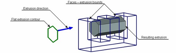
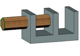
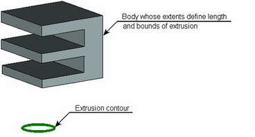
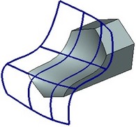
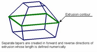
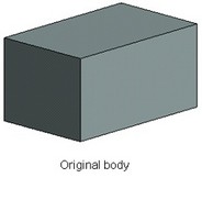
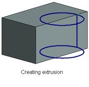
Extrusion operation creates solids by sweeping the shape-defining element – the extrusion contour. Extrusion is a most popular operation across solid modeling systems.
The operation supports two types of extrusion: extruding along an arbitrary vector, and extruding in the normal direction to the base contour surface. The extrusion type determines the direction assignment and the ways of extrusion creation.
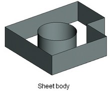
The extrusion contour can be made of wire or sheet geometry objects. The result of extruding is a sheet or solid body, depending on the type of the contour geometry.
The extrusion length (or extrusion start and end) can be defined by various means, including bounding by other model elements.
Main concepts. Operation capabilities
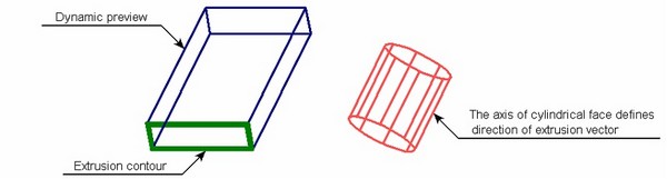
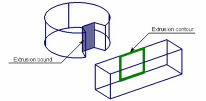
Extrusion contour
The extrusion contour can be made of wire and sheet geometry objects. Several elements can be selected simultaneously. In this case, the elements are joined first, and then extruded together. However, only same-type objects are allowed in the selected group of elements, either all wire or all sheet objects. These include 3D profiles and faces, or paths and edges.
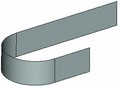
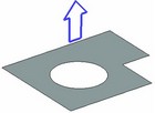
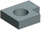
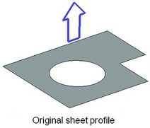
The result of extruding a wire contour is a sheet body. Extrusion of a sheet contour makes a solid body.
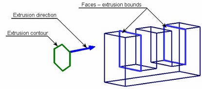
Extrusion direction
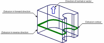
The trajectory of sweeping the contour for extrusion is defined by the extrusion direction. Depending on the extrusion type, the direction can be defined by the normal to the original contour surface or an arbitrary vector.
In either case, there are the forward and reverse directions of sweeping the contour. The forward direction coincides with the normal direction or the extrusion vector. Reverse is the direction opposite to the forward one. Two-sided extrusion is also supported, in which the contour is swept in both directions. By default, the system creates extrusion in the forward ("first") direction.
Extruding in normal direction
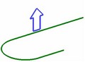
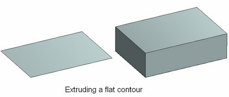
Extruding along the normal is the system default when selecting a sheet or flat wire contour. Each point on the contour is swept along a separate line defined by the normal direction to the contour surface at the point. In this case, extrusion can be described as an offset from the original contour defined by the specified length of the extrusion.
In real life, flat contours are extruded most often, with the same normal direction at all points of the contour. For practical purposes, one can think of the flat contour in this case being translated parallel to its original position along one common line defined by the single normal to the contour plane. Therefore, extrusion normal to the flat contour can be viewed as a special case of extruding along an arbitrary vector.
Extruding along an arbitrary vector
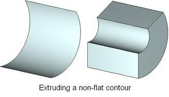
When the extrusion direction can't be defined by the normal (for example, if a non-flat wire contour was selected) or extrusion is desired in a specific direction, then its definition may include an arbitrary direction vector.
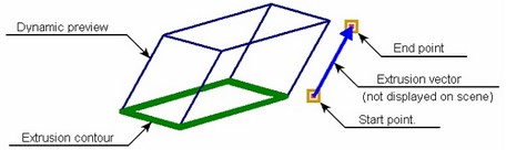
The vector of the extrusion direction can be defined in two ways:
1) By specifying a pair of 3D points (the vector start and end);
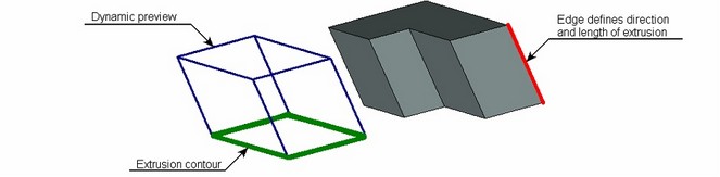
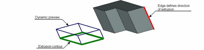
2) By selecting some element of the 3D model suitable for defining a vector in the desired direction (regardless of the length).
Two 3D points define the start and end of the extrusion direction vector. 3D points can be defined by 3D nodes and vertices. One can also select other elements defining the desired point. For example, one can select an edge – in this case, the edge midpoint will be used as the 3D point. Selecting a coordinate system defines the point at the origin. Selection of a face, which is part of a sphere or torus – yields the point at the center of the sphere/torus, and so on.
In the latter approach, the selected 3D object defines the vector of extrusion direction. The suitable kinds of objects are flat curved edges, workplanes, flat faces, surfaces (the direction is determined as the normal to the selected element), straight edges (the vector coincides with the selected edge), coordinate systems (the direction is one of the axes), faces/surfaces that are part of a cylinder or a torus (the direction of the vector is the direction of the face/surface axis).
Defining extrusion length
The length of an extrusion can be specified in one of the three ways:
1) By the length of the defining vector of the extrusion direction;
2) By an arbitrary numerical value, measured from the original contour position;
3) By an offset from a 3D point or a plane;
4) By extrusion bounds.
Defining extrusion length by length of direction vector
The extrusion length can be derived from the length of the defining vector of the extrusion direction in the cases when the direction is defined by two 3D points or a straight edge. The length of the extrusion vector in this case is defined by the distance between the specified points or the length of the selected edge. Extruding is performed from the original contour position straight by the amount equal to the vector length. The length of extruding in the reverse direction, if necessary, can be defined by an arbitrary number or set equal to the length of extruding in the forward direction.
Defining extrusion length by numerical value
Regardless of the ways of defining extrusion direction, the extrusion length in the forward direction (from the original contour position) can be defined by an arbitrary numerical value. The extrusion length in the reverse direction, if necessary, is defined by an arbitrary numerical value or is set equal to the length of extruding in the forward direction.
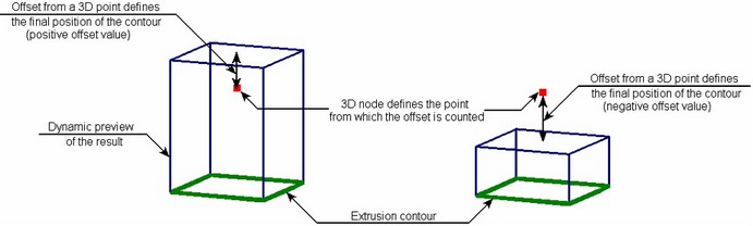
Defining extrusion length as an offset from a 3D point or a plane
An extrusion length can be defined as an offset from an arbitrary 3D point or a plane only in the case of a flat contour being extruded in the normal direction. The extrusion is performed from the original contour position to the position defined by the offset.
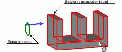
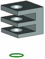
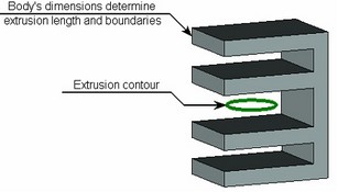
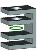
Defining extrusion length by extrusion bounds
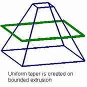
When specifying the extrusion length with the help of bounds the extrusion is performed from one boundary to another.
Types of bounds
The bounding conditions can be of the following types:
Offset from the original contour plane |
The body being created is bounded by a plane parallel to the original profile, at the specified distance from it |
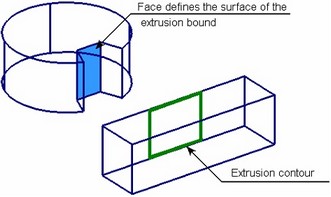
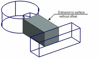
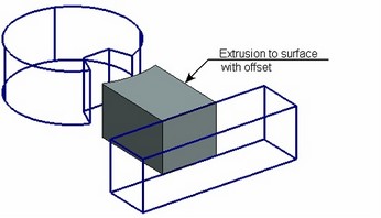
To surface |
The body being created is bounded by the specified surface |
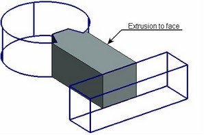
To face |
The body being created is bounded by the specified face |
To body |
The body being created is bounded by the specified solid body |
To nearest face |
The body being created is bounded by the nearest face of the specified solid body in the given direction |
Through all body |
The body being created is bounded from both sides by the specified solid body |
To sheet |
The body being created is bounded by the specified sheet body |
Through all body by direction |
The body being created is bounded on one side by the original profile position, whereas on the other side - by a specified solid body |
For the extrusion to be created successfully to the specified bounds, make sure that the extrusion contour fully reaches the 3D element specified as an extrusion bound.
Offset from the original contour plane
An offset from the original contour plane can be specified as one of the extrusion bounds. In this case, the extrusion is bound by the specified distance from the original contour.

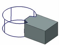
Bounding by surface
One of the bounds can be defined by a workplane or surface. Also allowed is a face, flat edge or simple body (a body with all faces on one surface) – in this case the extrusion bound is defined by the geometrical surface where the selected element belongs.
The extrusion being created is bounded by the whole surface. If the surface was identified by an element belonging to it, the surface is extended beyond the element limits whenever possible. Some complex surfaces, such as an underlying surface of a body face defined by a spline, like those created in the "Loft" operation, can't be extended. In this case, the surface limits coincide with the limits of its defining object.
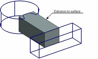
Additionally, one can impose an offset from the specified surface (positive offset is at the outer side of the surface).
Bounding by face
If "to face" bound is selected, the body being created is extruded in the specified direction and is bounded by the specified face. If the contour only partially intersects with the selected face, the adjoining faces are used for bounding as well.
Bounding by body
A solid body can be specified as an extrusion bound. The body being created is extruded in the specified direction until it intersects with faces of the specified body. Bounding of the extrusion is done in the same way as in the case of a specific face bound.
If the bounding body intersects with the body being created several times, the intersection is processed that was nearest to the position of the cursor when clicking the body for selection.
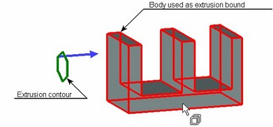
Bounding by body is a more robust technique then bounding by a specific face, because different faces may act as the extrusion bounds upon changes in topology of the selected object. (The face selected as a bound at the time of extrusion creation may later shift or disappear altogether.)
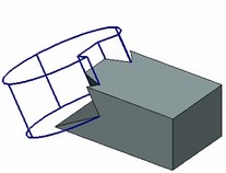
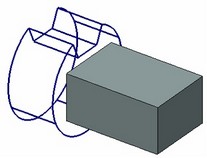
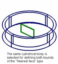
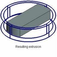
Bounding by nearest face
A special case of extruding to body is extrusion to nearest face of the body in the specified direction. In this case, it is always the first intersection with the selected body in the specified direction of extruding (forward or reverse).
The following conditions need to be observed when defining this kind of bounding:
1) The specified extrusion bounds (at least one of which is the "To nearest face") must be on different sides of the original contour. An exception from this rule is the case when the second extrusion bound is defined by an offset from the original contour plane.
2) The body, whose nearest face will be the extrusion bound, must be in the forward direction from the original contour, when it defines the first bound, and in the reverse direction, when defining the second bound.
Through all body
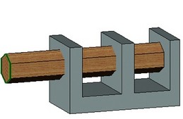
Yet another variation of extrusion bounding by intersection with a solid body is "Through all" bound type. What is special in this case is simultaneous definition of both extrusion bounds and required simultaneous imposing of Boolean subtraction or intersection. The amount of extruding is defined by the size of the selected bounding body. This body will be used as the target body for the Boolean. This technique can be used, for example, when creating through holes in a body.
Through all body by direction
This method of bounding an extrusion is very similar to the previous one. The only difference is that in this case the extrusion is performed only in the forward direction from the source contour position. Therefore, the resulting body is bounded on one side by the source contour position, whereas on the other side - by the selected bounding body. As in the previous case, this method requires a simultaneous Boolean subtraction or intersection.
Bounding by sheet body
Bounding of an extrusion by a sheet body is done similar to the general case of bounding by a solid body. An operation (surface), face or a 3D profile can be selected as an extrusion bound. The body being created is extruded in the specified direction until the intersection with the specified sheet body. If the sheet body intersects with the one being created several times, the intersection is processed that was nearest to the position of the cursor when clicking the body for selection.
Add-on extrusion features
Creating tapers
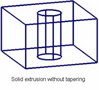
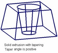
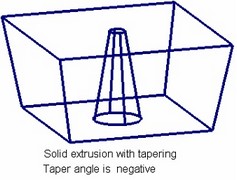
Tapers can be applied automatically on the side faces while creating an extrusion. All side faces of the body being created are slanted from the original position by the specified angle.
The direction of tapering depends on the specified angle and body type. If the resulting extrusion is a solid body then positive angle values correspond to tapering toward the inside of the body. For the opposite result, specify a negative tapering angle.
When creating a sheet body, the choice of taper direction is left out to the system. If the system choice is different from the desired, simply change the angle sign.
The taper angle can be defined either separately for each extrusion side (if the extrusion length was defined by a numerical value or direction vector length), or once for the whole extrusion (if the extrusion length was defined by specifying bounds).
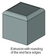
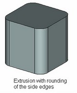
Creating blend
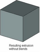
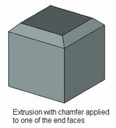
While extruding, the created side edges can be instantly blended. In the case of solid body extrusion, rounds or chamfers can also be applied at the end faces of the resulting extrusion.
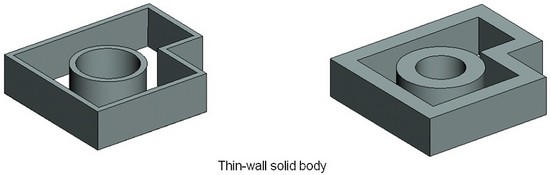
Creating thin walls
Use of an additional mode of thin wall element creation yields a different extrusion. As a result, a body is created similar to that created by the "Shell" operation. This mode is only available when extruding flat contours.
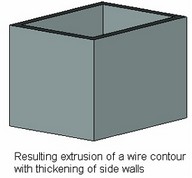
As any flat contour is extruded in the thin wall mode, a sheet body extrusion is created initially. Thereafter, it is processed depending on the selected wall type:
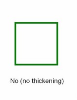
● No thickness – the resulting extrusion is left as is (used for creating a sheet body based on a sheet contour; for a wire contour, the result is the same as in regular mode);
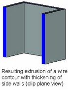
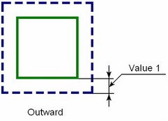
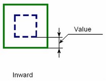
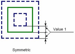
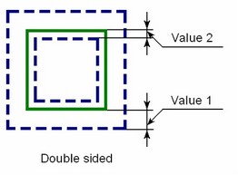
● With thickening the side walls by various means (inward, outward, symmetric, double-sided with different thickness in the outward and inward directions from the original face) – this creates a thin-wall solid body from the sheet body by thickening the walls.
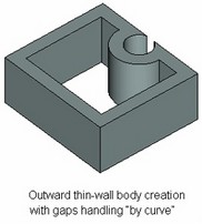
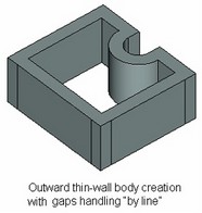
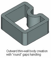
The new faces in the thin-wall body are created by extruding an offset contour of the original one. The shape of the faces depends on the choice of handling the gaps when creating an offset contour:
By curve – The offset curves of the original contour are prolonged until intersect.
By line – The offset curves of the original contour are extended at their free ends by tangent line segments.
Round – The free ends of the neighboring offset curves are connected by rounds.
Creating "bottom" and "top"
As a thin-walled body is created, only side walls exist. If necessary, one can automatically add "bottom" and "top" – the capping walls of specified thickness to the resulting body.
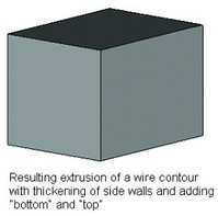
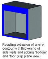
This feature is not available when boundaries are specified for the extrusion.
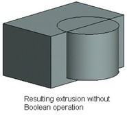
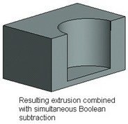
Using created body in Boolean operation
To speed up modeling, an option is provided for combining an extrusion being created with a simultaneous Boolean operation.
Creating extrusion operation
Extrusion operation is created by the command "3X: Create extrusion". The command can be called in one of the following ways:
Icon |
Ribbon |
|---|---|
|
3D Model → Create → Extrusion |
Keyboard |
Textual Menu |
<3X > |
Operation > Extrusion |
The automenu and the property window are used together in the command. These work together and enhance each other. The state of the automenu depends on the current step in defining the operation and on the purpose and type of the objects being selected.
The following steps are to be done to create the operation:
1. Select extrusion contour
2. Define extrusion direction (optional when extruding in normal direction)
3. Define the length or extrusion bounds (optional in some cases)
4. Define additional parameters (taper, blend, thin-wall mode, create Boolean operation) (optional)
5. Confirm operation creation
Selecting extrusion contour
To create the operation, first define the extrusion contour. Upon calling the command, the following option automatically activates in the automenu:
![]() <R> Select Contour
<R> Select Contour
This option contains a list of filters for selecting 3D element allowed as extrusion contour: loop, edge, face, 3D profile and other wire and sheet objects. When selecting elements, pay attention to the active filters. Use of filters is described in details in the chapter "Basic 3D terms and principals of modeling with T-FLEX CAD 3D".
To define the extrusion contour, move the cursor over the desired element in the 3D window. The pointed at element will be pre-highlighted, and the cursor gain a tooltip with the element name. Click ![]() to select.
to select.
3D profiles that are based on hatches can be selected by picking the original hatch in the 2D window.
Upon selecting the extrusion contour, the option will appear in the automenu for rejecting the contour:
![]() <H> Cancel contour selection
<H> Cancel contour selection
Calling the command with automatic contour selection
A slick way of handling an extrusion is calling the command with automatic selection of the extrusion contour.
Enter the "drawing on workplane" mode (see the chapter "Workplanes") and draw the extrusion contour.
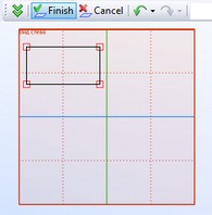
Then, without leaving the active workplane mode via ![]() , call the command "3X: Create extrusion". The system will then automatically create a 3D profile based on the "continuous"-type graphic lines or a hatch, and will select it as the extrusion contour.
, call the command "3X: Create extrusion". The system will then automatically create a 3D profile based on the "continuous"-type graphic lines or a hatch, and will select it as the extrusion contour.
Defining extrusion direction
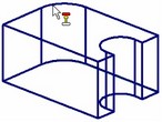
Upon selecting a sheet or flat wire contour, the system automatically offers to create an extrusion in the normal direction. This is indicated by the wireframe preview of the body being created, displayed on the 3D scene. There is no need in this case for defining the extrusion direction. The user can alter the kind of extrusion simply by defining a different extrusion direction by specifying a direction vector.
If a preview is not displayed on the 3D scene, extrusion in the normal direction can't be created from this contour.
The following option lets define extrusion direction vector by a 3D model element:
![]() <D> Select Direction
<D> Select Direction
This option lets select a 3D element suitable for defining the extrusion direction vector. The pull-down list under this option contains filters for selecting respective objects. When selecting elements, pay attention to the active filters.
The following automenu options let define the extrusion direction vector by two 3D points (activate sequentially):
![]() <F> Select starting Point of Extrusion
<F> Select starting Point of Extrusion
![]() <S> Select ending Point of Extrusion
<S> Select ending Point of Extrusion
A 3D point can be defined by selecting a 3D node, a vertex on a body, profile or path. Besides, selecting an edge yields the edge midpoint as the 3D point (for straight edges) or the center (for edges that are full circles, arcs or ellipses). Selecting a face that is part of a sphere or torus yields the sphere/torus center as the point. A coordinate system selection yields the origin as the 3D point. The set of the elements allowed for selection is defined by the state of the selection filters in the pull-down lists of the mentioned options. Besides the automenu options, directions can be defined via the property window dialog. The ![]() button in the dialog helps quickly change the direction of the selected vector or the surface normals to the opposite. The last option in the direction-defining group of the automenu rejects the vector selection:
button in the dialog helps quickly change the direction of the selected vector or the surface normals to the opposite. The last option in the direction-defining group of the automenu rejects the vector selection:
![]() <K> Reset Direction selection
<K> Reset Direction selection
Defining extrusion length
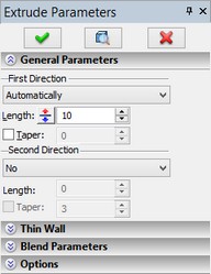
The means of defining the extrusion length is selected in the section "General Parameters" of the command property window. This section contains two groups of parameters – "First Direction" and "Second Direction". Each group contains a list of options for the ways of defining the length in the specified direction or the types of bounding conditions.
Manipulator of extrusion
To specify the length and also the direction of the extrusion, it is possible to use the special manipulator in the form of a large two-directional arrow colored in two colors. Positive direction of the extrusion is marked with red color, negative – with blue color. Manipulator has the context menu (invoked by pressing ![]() ) in which the additional options are available:
) in which the additional options are available:
●setting the step of the manipulator;
●displaying additional elements of the manipulator – small spheres at the arrow ends (used for specifying the direction of the extrusion with two 3D points);
selection of the type of the extrusion bounds (of the bounding surface, face, Body).
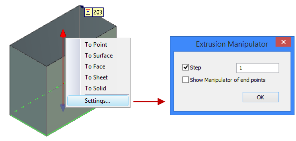
All elements of the manipulator (the axis of the arrow, arrow ends in the form of cones or the hidden by default points-spheres at the arrow ends) have their own functionality. Clicking the sphere at the arrow end transfers the command into the mode of specifying the first and the second points of the extrusion direction. Clicking the axis of the arrow transfers the command into the mode of selection of the extrusion direction. Clicking the arrow end (cone) or dragging the arrow allows us to specify the bounds of the extrusion by the numerical value or via fixing to a geometric point.
Defining extrusion length by direction vector length or numerical value
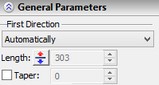
The default option for extruding in the first (forward) direction is "Automatically". It allows the system to automatically choose a means of defining the extrusion length in the first direction (depending on the way of defining the extrusion direction).
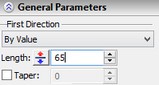
When defining the extrusion direction by a vector, the system tries to define the extrusion length in the first direction by the vector length. This is possible only when the vector is defined by two 3D points or a straight edge. The input box of the extrusion length in the first direction becomes inaccessible for editing. The numerical value displayed in this box reflects the value derived from the vector length. To override this mode, one can force the extrusion length input mode (in the first direction) by a numerical value. To do this, simply change the option of defining the length to "By value". |
|
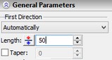
When defining the direction vector by other means (for example, by the axis of a cylindrical face or normal to a surface), as well as in the case of normal extrusion, the extrusion length can't be defined by the length of the direction vector. In this situation, the system will offer to enter the extrusion length as a numerical value. The "Length" input box will become accessible for input. In it, specify the desired value of the extrusion length (in the first direction). |
|
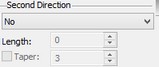
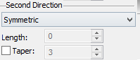
By default, extruding is not performed in the second direction. The "Second Direction" group has the option "No" set in this case. The input boxes of the extrusion length and taper in the second direction are inaccessible. |
|
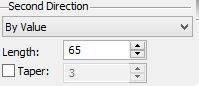
To perform extruding in the second direction, select another option of defining the length from the list. To have the extrusion length in the second direction equal to the extrusion length in the first direction, select the option "Symmetric". The "Length" input box stays inaccessible in this case. To define the extrusion length in the second direction by an independent numerical value, select the option "By value". The value input box will become accessible. |
|
The wireframe preview on the 3D scene shows the resulting extrusion with the specified parameters. Besides, it allows inputting the value of the extrusion length both in the first and in the second direction directly on the 3D scene by the mouse.
As the cursor approaches the preview of the body being created, it gets marked as ![]() (for extruding in the first direction) or
(for extruding in the first direction) or ![]() (for extruding in the second direction). Dragging the mouse with the depressed
(for extruding in the second direction). Dragging the mouse with the depressed ![]() dynamically changes the extrusion length. The numerical value of the current length is reflected in the property window.
dynamically changes the extrusion length. The numerical value of the current length is reflected in the property window.
The sampling of mouse input depends on the amount of zoom into the object. For example, by zooming in one can refine the sampling step by 10 times.
Note that in the mode of defining the length of for extrusion in the first direction by the length of the extrusion vector, the wireframe preview on the 3D scene allows to change dynamically only the length in the second direction. In the case of the extrusion length in the second direction being defined by the option "Symmetric", the length in that direction can't be modified by the mouse either.
Defining extrusion bounds
The mode of defining the length by boundaries is represented with the following items in the lists of methods to define the extrusion length: “Through All”, “Through All by Direction”, “To Surface”, “To Face”, “To Body”, “To Sheet”, “Offset”, “To Nearest Face”.
Defining extrusion bounds is done by combined use of the property window and the automenu. In the general parameters of the property window, select the type of each bound in the first and second direction. Parameters of each bound can also be defined there, if necessary.
The names of the groups ("First Direction", "Second Direction") for specifying bounds are essentially arbitrary. The bound positions are generally not related to the extrusion directions. The exception here is the bounding condition of the "Nearest face" type that is defined for a particular extrusion direction.
After selecting the bound types, one of the following options become available in the automenu:
![]() <T> Select 1st limit of extrusion
<T> Select 1st limit of extrusion
![]() <B> Select 2nd limit of extrusion
<B> Select 2nd limit of extrusion
These options are used for selecting 3D elements defining the bounding conditions. These options may have pull-down lists containing filters for selecting 3D elements. The presence and contents of a list are determined by the specified type of the respective bound.
The last option in this automenu group rejects the selection. Depending on the state of the command, this may be one of the following icons of rejecting a bound:
![]() <U> Discard 1st extrusion limit
<U> Discard 1st extrusion limit
![]() <U> Discard 2st extrusion limit
<U> Discard 2st extrusion limit
![]() <U> Discard extrusion limits
<U> Discard extrusion limits
The option ![]() is available while defining the first bound (under the active option
is available while defining the first bound (under the active option ![]() ). The option
). The option ![]() is available while defining the second bound (under the active option
is available while defining the second bound (under the active option ![]() ). In other states of the command (for example, under the option of contour or direction selection), the option is displayed for rejecting both bounds
). In other states of the command (for example, under the option of contour or direction selection), the option is displayed for rejecting both bounds ![]() .
.
When using bounds, the extrusion direction vector is displayed in the 3D window by a blue arrow. The elements selected as bounds are also outlined (by default, in blue color).
The wireframe preview of the extrusion being created won't be displayed in this case. To preview the resulting operation, use the preview option in the automenu or the respective button in the property window:
![]() <F5> Preview Operation Result
<F5> Preview Operation Result
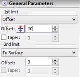
The type of the first bound can be selected among extrusion parameters in the first direction. The following options can be selected from the list:
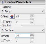
Offset. This is the condition type "Offset from the original contour plane". In the extrusion parameters, enter the value of the offset from the original contour plane in the "Offset" input box. To surface. This is the condition type "To surface". On the 3D scene, select a worksurface/workplane, face, flat edge, simple body or profile. The list of elements allowed for selection is defined by the state of the filters of the option If necessary, one can enter the value of the offset from the specified surface in the "Offset" input box. |
|
To face. This is the condition type "To face". On the 3D scene, select a bounding face for the extrusion.
To body. This is the condition type "To body". On the 3D scene, select a bounding body for the extrusion. If the bounding body intersects with the extrusion several times, the intersection is processed that was nearest to the position of the cursor when clicking the body for selection.
To nearest face. This is the condition type "To nearest face". On the 3D scene, select a body with the nearest to the extrusion face serving as the extrusion bound.
The specified body must be located properly. For the first bound, the selected body should be in the first extruding direction from the extrusion contour. For the second bound, the body should be in the second direction.
Through all, Through All by Direction. These are the conditions of the types “Through all body” and “Through all body by direction”, respectively. These boundary conditions do not require the second bound definition.
If any of these types of boundary conditions is used, then the mode of creating a Boolean operation (“Subtraction” or “Intersection”) is enabled automatically. The body, whose extents define the extrusion length, is treated as the target body for the Boolean.
To sheet. This is the condition type "Bounding by sheet body". On the 3D scene, select a sheet body, face or 3D profile. The list of elements allowed for selection is defined by the state of the filters in the option ![]() .
.
The type of the second bound is defined among the extrusion parameters in the second direction in the same way. The list of 3D elements allowed for selection for each type of the bounding condition is defined by the state of the option ![]() .
.
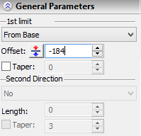
Defining extrusion length by an offset from a 3D point or a plane
This method of defining an extrusion length is used, if the “From Base” item is chosen in the properties window or one of the following options is selected in the automenu:
![]() <Ctrl+N> Select Starting Point of Extrusion
<Ctrl+N> Select Starting Point of Extrusion
![]() <Ctrl+P> Select Plane setting starting position of Extrusion
<Ctrl+P> Select Plane setting starting position of Extrusion
Both options have drop-down lists with the filters to select geometrical objects defining a 3D point or a plane.
A point or plane selection can be canceled using the option:
![]() <Ctrl+F> Cancel selection of Extrusion Base
<Ctrl+F> Cancel selection of Extrusion Base
Defining add-on operation features
The result of add-on extrusion features is not reflected on the preview of the body being created on the 3D scene. To preview those, use the option ![]() .
.
Creating tapers
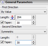
The value of the taper is entered in the property window. In the case of defining the extrusion length by an arbitrary numerical value or by the length of the direction vector, the separate values are specified for the tapers in the first and second direction.
To create a taper in either extruding direction, check the "Taper" item in the respective group ("First Direction", "Second Direction"). The input box then becomes accessible for entering a numerical value for the taper.
If the extrusion length is defined by bounds then tapering is uniform across the extrusion extents. Its numerical value is defined in the group of the first extrusion bound (the "First Direction" group).
Creating edge blends
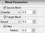
The parameters of various blends can be defined in the "Blend Parameters" section of the property window:
The "Target Blend" and "Source Blend" groups define blending parameters on the end faces of the extrusion. To create a blend, check the respective item, select a blending type from the list – "Round" or "Chamfer" and specify the amount of blending.
The source face is considered the first end face when moving through the extrusion along the first extruding direction.
The "Fillet" flag sets the mode of rounding side edges of the extrusion. The rounding radius is defined by the "Radius" parameter.
Creating thin walls, "bottom" and "top"
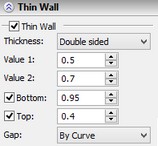
The parameters of the thin-wall extrusion can be defined in the section "Thin Wall" of the property window. To turn on the mode of thin-wall body creation, check the item "Thin Wall". With the item checked, the following parameters of this mode become accessible:
Thickness. Defines the way of thickening the walls of the thin-wall body being created. The following options can be selected from the list: No. Without thickening of the side walls (the resulting extrusion will be a sheet body). Outward, Inward, Symmetric, Double sided. Define various ways of thickening. The result of using each of these options is shown on the diagrams. The wall thickness is defined by the parameters "Value 1" and "Value 2". |
|
The ways of handling the gaps between the created offset faces are defined by the parameter "Gap": "By line", "Round", "By curve".
To create the "bottom" and "top", check the respective items in the dialog and specify the desired thickness of these elements.
Using the created extrusion in a Boolean
To create a Boolean operation, do the following:
1. Turn on the Boolean creation mode by the automenu option
![]() <Ctrl+B> Select original body for Boolean operation
<Ctrl+B> Select original body for Boolean operation
A Boolean is created when the icon is pushed.
2. Select the type of the operation from the pull-down list under the above option:
![]() <Ctrl+'+'> Addition
<Ctrl+'+'> Addition
![]() <Ctrl+'-'> Subtraction
<Ctrl+'-'> Subtraction
![]() <Ctrl+'*'> Intersection
<Ctrl+'*'> Intersection
![]() <Ctrl+l> Smart mode
<Ctrl+l> Smart mode
Operating principles of the Smart mode:
●If the body being created and the existed selected body have intersection of volumes - the type of Boolean operations: subtraction.
●If the body being created lies entirely within the selected body - the type of Boolean operations: subtraction.
●If the body being created touches and selected body touch each other - the type of Boolean operations: addition.
●If conditions set out above are not met, or a selected body lies inside the created, or error occurred determining the type of penetration, then, Boolean type is not defined - the Boolean operation will not be created.
3. Select the target body for the Boolean (optional in some cases), using the automenu option
![]() <Ctrl+T> Select Target Body for Boolean
<Ctrl+T> Select Target Body for Boolean
If only one body exists in the scene, it is selected automatically. The new body created by the extrusion operation becomes the tool body of the Boolean.
Upon confirming operation creation, first the body is created by the extrusion operation, and then the specified type Boolean is performed.