Constraints


Constraints |
|
Creating a Sketch with Constraints (Variation Parameterization of Sketch)
Thanks to the tools of variation design, it became possible to define connections between geometric elements (lines, circles, curves, etc.) by means of constraints — geometric and dimensional relationships.
Keyboard |
Ribbon |
|---|---|
<SC> |
Draw → Constraints |
Icon |
Textual Menu |
|
Draw > Constraints |
Constraints Types.
Horizontal and Vertical Alignment
Methods for creating Automatic Constraint.
Infer Constrains (Automatic constraining in process of sketching)
Find and Infer Constraints (Automatic constraining on existing sketch)
Special Constraints.
All possible variants of geometric relations are in a separate block of the Ribbon. To set or remove constraints between elements, you can change the values of the model parameters at any time while designing. |
|
Geometric elements do not have a rigid hierarchical relationship and therefore constraints can be freely assigned between them in any order.
To create a parametric sketch based on constraints and driving dimensions, you need to create the basic geometric elements of the future model using Sketch command. It is not necessary to immediately define the relationship between the elements of the drawing.
Constraints and dimensions for created items can be created automatically. Automatically created dimensions and constraints can be replaced by others. By default, automatic constraints are disabled for 2D, and enabled for 3D. Automatic dimensioning for both 2D and 3D is disabled.
You can enable and disable automatic constraints and automatic driving dimensions on the bindings panel, using icons ![]() and
and ![]() .
.
The list of automatically created constraints can be changed: Settings on the “Constraints and Dimensions” tab in the “Automatically create constraints” and “Automatically create dimensions” sections, you can specify or exclude some types of constraints and dimensions.
Icon |
Ribbon |
|---|---|
|
Constraints → Constraints and Dimensions Settings |
When creating constraints in the sequence of selecting graphic lines and points, there is no hierarchy: to fulfill the constraint, both the whole line and only its characteristic point can move (by changing the line to which it belongs), both the first selected element and the second one can move. This is connected with the very idea of variable parameterization, when the entire set of possible geometrical positions corresponds to each interrelation (constraint) of elements. To specify all interrelations between lines, geometry of lines and their position on a plane, you need to specify the required number of constraints and driving dimensions.
If upon creation of the drawing construction lines are used it is necessary to remember - they have priority. When editing a drawing, the construction lines will act as constants, relative to which the sketch will be parametrically rearranged. In this case, the parameterization of the construction lines themselves will be preserved, having priority over the lines of the sketch.
The following rule should be used.
You can snap sketch lines to construction lines, but you cannot tie construction lines to sketch lines.
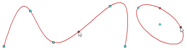
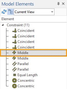
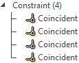
The created constraints can be seen as in the drawing - they are displayed with icons similar to icons in the Ribbon, as well as in the “Model Elements” window. The icons in the drawing are located next to those points and lines to which the corresponding limiting relationships are applied. In the "Model Elements" window, you can highlight any constraint- then the drawing will highlight those lines and points to which this constraint is imposed, as well as the icon for this constraint. A similar highlight will appear if in the drawing field you move the cursor over the constraint icon.
|
|
The context menu of the constraint can be accessed by clicking ![]() on it in the “Model Elements” window or by clicking
on it in the “Model Elements” window or by clicking ![]() on the constraint icon in the drawing. The context menu for constraints contains a standard set of options and commands, similar to the options and commands for construction lines and sketch lines. Consider only options and commands specific to constraints.
on the constraint icon in the drawing. The context menu for constraints contains a standard set of options and commands, similar to the options and commands for construction lines and sketch lines. Consider only options and commands specific to constraints.
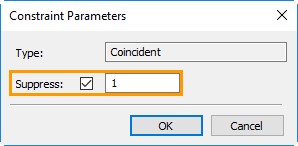
For any constraint, you can call its parameters ("Constraint properties"). The window will contain the name of the constraint and the ability to suppress the constraint by setting the flag in the appropriate field. You can also put the Suppress command on the variable. You can also suppress the constraint through the context menu. If the constraint is suppressed, then there will be a special icon next to the constraint. Similar icon appears on the drawing.
|
|
Using the context menu, you can remove the constraint. You can also remove the constraint by highlighting its icon in the drawing with ![]() , and then pressing the <Del> key.
, and then pressing the <Del> key.
Sketch Lines Degrees of Freedom
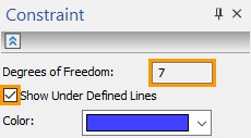
Constraints specify the absolute and relative position of the drawing lines in the drawing. In other words they limit the degrees of freedom of graphic lines and their characteristic points. The number of degrees of freedom of the drawing can be viewed in the properties window of the constraints when invoking any constraint. The number of degrees of freedom determines the number of translation options for all lines in the drawing. For example, if you draw a segment, then it will have four degrees of freedom: we can change its length, move it vertically and horizontally and rotate. Otherwise: its end points have two degrees of freedom. If you fix one point, then the degrees of freedom will be 2: only one point will have 2 degrees of freedom, or else - the segment can only be rotated and its length changed. If, in addition to fixing the point, you fix the length of the segment, then one degree of freedom will remain rotation of a segment or moving a point along a circle.
If you draw a circle, then it will have 3 three degrees of freedom: moving vertically and horizontally, as well as changing the radius. If segment and circle are in the drawing there will be 7 degrees of freedom.
The properties window always displays the total number of degrees of freedom of the drawing, taking into account the constraints created.
|
|
To understand which graphic lines still have degrees of freedom in the properties window of constraints, there is a special option Show under defined lines. The option is enabled by setting the flag. Then on the drawing the selected color (blue by default) will highlight all lines that have at least one degree of freedom.
|
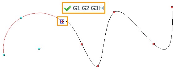
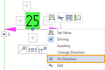
If the sketch is completely defined, i.e. if it does not have degrees of freedom, then the icons of the coincidence constraint will be displayed in green, and the control dimensions will be on a green background. When creating parametric models, it is extremely important to fully define the sketch. When changing driving parameters, all undetermined lines will be rearranged randomly. |
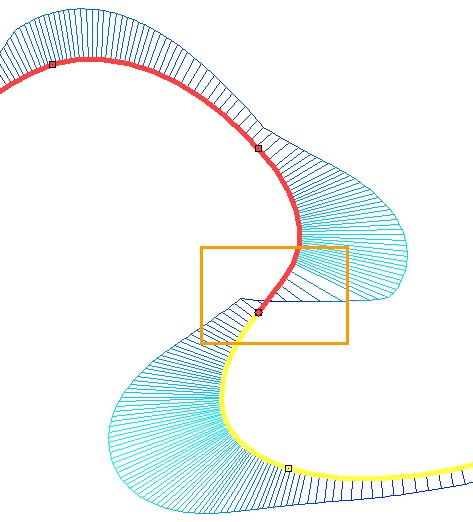
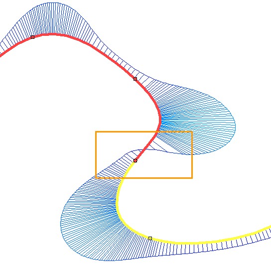
Another important point in the parameterization of the sketch with the help of constraints and control dimensions is the fixing of the direction of the driving dimensions.
If, in parametric constructions, the control size specifies the distance between the lines, which as a result of the parametrization can change their position, then it is necessary to fix the direction of the control size.

Otherwise, the relative position of the elements after rebuilding can be reversed.
This constraint creates a connection between two points (one of the points can be the origin) or between a point and a line. The point of one object will coincide with the point or line of another object.
Icon / Keyboard |
Ribbon |
|---|---|
|
Constraints → Coincidence |
If points (or point and line) do not coincide when constructing a sketch, then when using the constraint Coincidence, lines will automatically move to such a position that the points (or point and line) coincide.
If the point is bound by Coincidence with another point or line, then any editing or parameterization will keep the coincidence.
The constraint can be set simultaneously for several points (or for several points and lines).
Examples
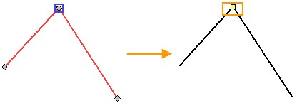
The coincidence of the ends of the segments
Select the first point of the end of the segment with ![]() , the second point of the beginning of another segment with
, the second point of the beginning of another segment with ![]() and end the input
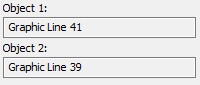
and end the input ![]() or press <Ctrl + Enter>. The order of points is not important. The properties menu will show the selected objects.
or press <Ctrl + Enter>. The order of points is not important. The properties menu will show the selected objects.
|
|
A yellow square marker in the drawing indicates the coincidence. If the coincidence is set incorrectly, the marker will be red. The specified points coincide both before creating the constraint and after. The difference is that if we move any of the segments, the other segment will be rearranged so that the points coincide. When sketching without constraints, the segments would be independent of each other.
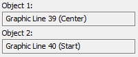
The coincidence of the segment and the center of the ellipse
Select the first point of the center of the ellipse with |
|
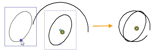
When moving a segment, the center of the ellipse moved with the starting point of the segment and the ellipse was rebuilt, since the center point shifted along with the cut, and the point defining its semi-axis remained in place.
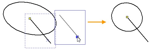
The coincidence of the end of a segment and a circle
Select the first point of the beginning of the segment with the help of |
|
You can change the position of the circle and its radius - the point of the beginning of the segment will always coincide with the circle.
Coincidence of Multiple Points
Select (in any order) points sequentially with |
|
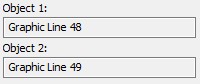
As a result, four constraints will be created for five points - for each pair of the second object with the first one. In the drawing, it will not be visible, because the constraint icons will be located one under the other, but this can be seen in the “Model Elements” window. Moving any of the five lines will rebuild the rest.
This constraint moves the points of the centers so that they coincide. This constraint can be applied to circles, arcs and ellipses. If arcs are obtained as a result of the Fillet or Offset Curve command, then the Concentric constraint can also be applied to them.
Icon / Keyboard |
Ribbon |
|---|---|
|
Limitations → Concentric |
Examples
Concentricity of Two Circles
Select the first line of the circle with the help of |
|
Now, if you move one circle, the second one moves so that the centers of the circles coincide.
Concentricity of Arc and Ellipse

First, select, for example, the arc line |
|
If you move, for example, an ellipse, then the arc is rebuilt so that its center and the center of the ellipse coincide, while the other two points defining the arc geometry remain in place. As a result, the arc geometry changes significantly. If it is necessary for some parameters of the arc to be preserved, you need to create additional constraints.
Concentricity of Several Lines
Concentricity can be created for several elements at once.
Select the lines with |
|
As a result, three constraints will be created for the four lines: each line of object 2 will be concentric with the line of object 1.
When moving any of the four lines or when editing a line that changes the position of the center, all elements are rearranged in such a way that their centers coincide.
The constraint moves the segments so that they are always on the same line. This constraint can be applied only to segments, including those that were obtained when constructing polygons or when using the Chamfer command.
Icon / Keyboard |
Ribbon |
|---|---|
|
Constraints → Collinearity |
Examples
Collinearity of Two Segments
Sequentially select the segments with the help of |
|
If the segments are located at a distance from each other, then a thin dashed line will be created between them. However, the segments may partially overlap one another, or the short segment will completely overlap the longer one.
When creating a constraint, an icon appears on the drawing that is similar to the one that invokes the command.
When editing one of the segments, the second one will change its position to stay in line with the first. In this case, the segments can begin to overlap or completely overlap one another.
Collinearity of Several Segments
Select the segments in any order with the help of |
|
Four constraints were automatically created for the five segments: one constraint for each pair of lines of object 2 with object 1. As in the case of two segments, editing or parameterization of any of the five segments will lead to a change in the position of the others.
This constraint moves the segments so that they are parallel. Parallel constraint can be applied only to segments with one exception: You can create a constraint between the axis of the ellipse and the segment.
Icon / Keyboard |
Ribbon |
|---|---|
|
Limitations → Parallel |
You can create the parallelism of two or several segments. When creating a constraint, icons appear in the drawing: one for each segment. The icon is similar to the icon in the Ribbon.
Examples
Parallelism of Several Segments
Select the segments in any order with the help of |
|
Five constraints were automatically created for the six segments: one constraint for each pair of object 1 lines with object lines 2. Each of the five segments is parallel to the first one - this is indicated using the icons in the drawing. When editing or set parameterization for any of the six segments, the positions of the others change in such a way that parallelism is preserved.
Segment and Axis of the Ellipse Parallelism
Having chosen the parallelism constraint, we select, with the help of ![]() , the line of the ellipse and the segment. When we select the line of the ellipse, two points that define the axis of the ellipse are visible.
, the line of the ellipse and the segment. When we select the line of the ellipse, two points that define the axis of the ellipse are visible.

If you edit a line or ellipse, the parallelism of the axis of the ellipse and the line will be preserved.
A constraint can be assigned practically between any lines in the drawing.
●Between two segments.
●Between a segment and a curve. In this case, the segment will be perpendicular to the tangent to this curve.
●Between two curves. In this case, tangents to these curves will be perpendicular.
The location of the tangent occurs randomly. This is due to the fact that for any curve you can hold an infinite set of tangents. If you want to determine the point where the tangent passes, to which the perpendicularity constraint will be assigned, then you need to impose additional constraints.
Icon / Keyboard |
Ribbon |
|---|---|
|
Constraints → Perpendicularity |
When creating a constraint, if the perpendicular segment does not intersect with another segment or is tangent to the curve, then a thin dashed line will be added to the intersection. The dashed line will also extend the arc to the intersection.
Example
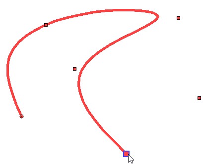
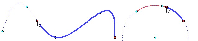
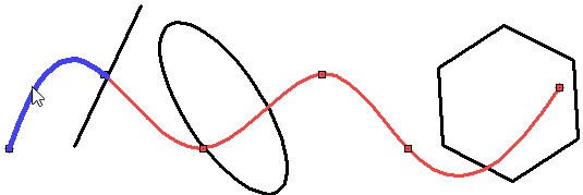
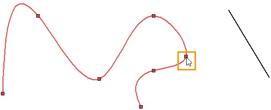
Perpendicularity of Segment and Spline at a Given Point
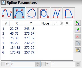
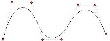
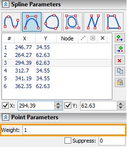
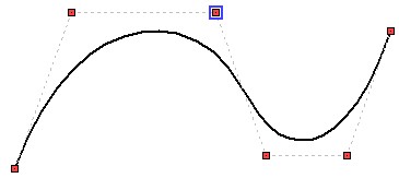
Let us be given a spline and we need to make sure that the segment to the right of the spline is perpendicular to the spline at the point under the cursor (was perpendicular to the tangent drawn to the spline at the point under the cursor).
If we set the limit of perpendicularity between the spline and the segment, then the point at which the segment will be perpendicular to the spline will be chosen randomly from an infinite set of possible ones. Therefore, you first need to set the Coincidence constraint and associate the start point of the segment and the specified spline point. Then only one intersection point with the spline will be specified for the segment. However, if you set the constraint of coincidence between a point on a spline and a point on a segment, then both a segment point and a spline point can move. If you move the spline point, the spline changes the geometry. Suppose it is undesirable for us. Then fix the spline. We use the Fix constraint for this (this constraint will be discussed later in the corresponding section). If during further work we do not need the constraint of fixation, then it can be removed.
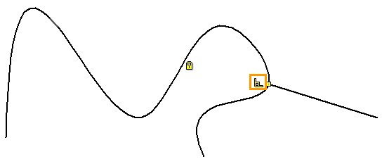
Thus, there is the following sequence of actions.
●Fix the spline by Fixation constraint.
●We combine the points of the beginning of the segment and the given point on the spline by the Coincidence constraint.
●Make the segment perpendicular to the tangent of the spline. To do this, select Perpendicularity constraint in the Ribbon. With the help of ![]() choose the lines of the spline and the segment, then we finish the input
choose the lines of the spline and the segment, then we finish the input ![]() or <Ctrl + Enter>.
or <Ctrl + Enter>.
|
|
|
|
The constraint can be created between any two sketch lines. The only exception is two segments. If there is no additional constraint, then there are infinitely many ways for the tangency of two lines. The point of contact will be determined randomly. In this case, the lines can change the geometry.
Icon / Keyboard |
Ribbon |
|---|---|
|
Constraints → Tangent |
Examples
Tangency of Ellipse and Circles
Let us be given an ellipse and two circles. Select the tangency constraint.

By pressing ![]() in an arbitrary order, select a circle and an ellipse. Since no additional constraints are specified, both the circle and the ellipse can move. The tangency can be from either side of the ellipse and the circle. As a rule, the constraint is created in such a way that the elements move along the shortest distance - i.e. in a straight line to the nearest possible point of contact. For example, if the initial position of the circle was different, then the point of contact would be different.
in an arbitrary order, select a circle and an ellipse. Since no additional constraints are specified, both the circle and the ellipse can move. The tangency can be from either side of the ellipse and the circle. As a rule, the constraint is created in such a way that the elements move along the shortest distance - i.e. in a straight line to the nearest possible point of contact. For example, if the initial position of the circle was different, then the point of contact would be different.

Finish typing using ![]() or <Ctrl + Enter>. An icon indicating the constraint of the tangency appears next to the point of contact. Next, by analogy, select the following two elements: ellipse and the second circle. We finish input - there is a new constraint. Again, as in the first case, the circle moved to the nearest point of contact.
or <Ctrl + Enter>. An icon indicating the constraint of the tangency appears next to the point of contact. Next, by analogy, select the following two elements: ellipse and the second circle. We finish input - there is a new constraint. Again, as in the first case, the circle moved to the nearest point of contact.
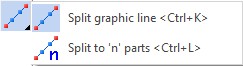
Create a Tangent constraint between two circles. We act by analogy: choose the circle with the help of |
|
By changing the initial position of the elements, you can define the sides of the tangency. For example, it is possible that the tangency of all three lines between them will be at a single point.

Segment Tangent to Arc at Given Point
Let an arc and a segment be given. It is necessary to make the segment tangent to the arc at the point of the beginning of the arc.
To begin with, we will create a Coincidence constraint so that the starting point of the arc is always on a segment. To do this, select a segment and a point with the help of ![]() . The constraint should be selected. We finish input of constraint objects. The elements will move so that the starting point of the arc lies on the straight line on which the segment lies.
. The constraint should be selected. We finish input of constraint objects. The elements will move so that the starting point of the arc lies on the straight line on which the segment lies.
Now create a tangency. Select the type of constraint Tangent, then with the help of ![]() choose a segment and an arc. Finish entering constraint objects using
choose a segment and an arc. Finish entering constraint objects using ![]() or <Ctrl + Enter>. The segment moves, the arc is rebuilt (the length is reduced).
or <Ctrl + Enter>. The segment moves, the arc is rebuilt (the length is reduced).
Now, with all editing or parameterization options, the segment (or the line on which the segment lies) will be tangent to the arc, at the point of the beginning of the arc.

This type of constraint fixes the selected element. You can select both a line and a point. Fixation and full fixation does the same for a point. The constraint Fixation for a sketch line fixes its position, angle and curvature. In this case, the length of the sketch line can be changed. Full Fixation constraint completely fixes the geometry of the sketch line, overlaying the fix automatically on its characteristic points. If a line or point is fixed, then when creating constraints or editing a parametric sketch, the selected line or point will be fixed.
Icon / Keyboard |
Ribbon |
|---|---|
|
Constraints → Fix |
|
Full Fixation |
Example
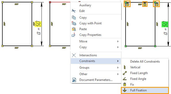
Full fixation is a quick way to fully define a sketch.
When creating parametric models, it is important to fully define the sketch. Otherwise, when the control parameters are changed, the under defined lines will be rebuild randomly. Restriction Full fixation makes it possible to fix those parts of the sketch that should remain unchanged in the parametric model.
Suppose we have a rectangle whose height is specified by the parameter “a”, while the length of the rectangle and the position of its upper side in the drawing must remain unchanged. We can call the context menu for the line of the upper side of the rectangle with the help of ![]() and select the constraint Full fixation. Considering other constraints (which can be created automatically when constructing a rectangle) and the driving dimension, the sketch will be completely defined. This is shown by a green background under the driving dimension and color of the Coincidence constraint points.
and select the constraint Full fixation. Considering other constraints (which can be created automatically when constructing a rectangle) and the driving dimension, the sketch will be completely defined. This is shown by a green background under the driving dimension and color of the Coincidence constraint points.
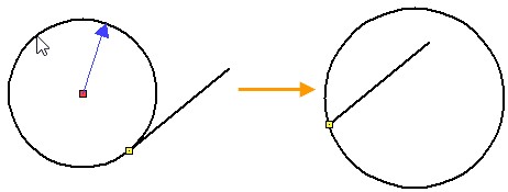
Fixing Lines When Creating Match Constraints
If you create a constraint Coincidence between the extreme points of the segments and segments of the polygon, then it can move as segments, as well as segments that are included into the polygon.
One of the options for applying the constraint Fix is the prohibition of moving selected elements when there is uncertainty, which of the selected elements in the pair should move.
In the tape, select Fix constraint. Using ![]() , we consecutive select all segments of the polygon, we complete the entry of constraint objects using
, we consecutive select all segments of the polygon, we complete the entry of constraint objects using ![]() or <Ctrl + Enter>. Five constraints will be created, which can be seen in the drawing by the icons that appear or in the “Model Elements” window. Then you can already create match constraints. Now only free segments have moved.
or <Ctrl + Enter>. Five constraints will be created, which can be seen in the drawing by the icons that appear or in the “Model Elements” window. Then you can already create match constraints. Now only free segments have moved.
|
|
The constraint can be applied to segments and arcs. Allows to keep the length of the segment or arc when editing a parametric sketch.
It is possible to select several lines, while in the mode of selecting objects of constraints. Number of created separate constraints of fixed length will be equal to number of the specified lines.
Icon / Keyboard |
Ribbon |
|---|---|
|
Constraints → Fixed Length |
Example
Arc Length Fixation
An arc is created by two points and a radius. Fix its length by Fixed length constraint. We select this constraint in the Ribbon, with the help of ![]() we select an arc, we create a constraint using
we select an arc, we create a constraint using ![]() or <Ctrl + Enter>. Next to the arc, an icon appeared indicating a fixed-length constraint.
or <Ctrl + Enter>. Next to the arc, an icon appeared indicating a fixed-length constraint.
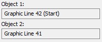
To make it easier to edit the radius and position of the arc, we fix the starting point of the arc. To do this, select the Fix constraint and specify the point. Now edit the arc. With the help of ![]() choose an arc, then a point
choose an arc, then a point ![]() . Now the end point of the arc follows the cursor. The length of the arc cannot change, the starting point remains fixed. Only the radius of the arc and its rotation relative to the first point changes.
. Now the end point of the arc follows the cursor. The length of the arc cannot change, the starting point remains fixed. Only the radius of the arc and its rotation relative to the first point changes.
The constraint can be applied to lines and ellipses. The constraint fixes the angle of a segment or the angle of the ellipse axis relative to the OXY coordinate system. The angle of the segment or axis of the ellipse at the time of application of the constraint is fixed. If the angle needs to be changed - it is necessary to remove the constraint, change the angle and fix it again. In the mode of selecting objects of constraint, you can specify multiple lines. Then upon completion of the input, number of constraints equal to the chosen lines will be created.
Icon / Keyboard |
Ribbon |
|---|---|
|
Constraints → Fixed Angle |
Example
Segment Angle Fixation
A segment is given. Fix its angle relative to the coordinate system of the drawing. To do this, select Fixed angle constraint in the Ribbon and specify segment using ![]() . When the creation of the constraint
. When the creation of the constraint ![]() is complete, an icon appears next to the segment. Before we try to edit a segment, we fix its bottom point — the effect of the constraints will be more obvious. To do this, in the Ribbon, select the Fix constraint and specify the segment point.
is complete, an icon appears next to the segment. Before we try to edit a segment, we fix its bottom point — the effect of the constraints will be more obvious. To do this, in the Ribbon, select the Fix constraint and specify the segment point.

Now we will try to change the geometry of the segment by moving the free top point. With the help of ![]() choose a segment, then the top point
choose a segment, then the top point ![]() . Now the segment point follows the cursor. Even if we move the cursor to the right or left - the point will only move along the straight line on which the segment lies. Restricting the angle fixation does not allow the segment to change the angle.
. Now the segment point follows the cursor. Even if we move the cursor to the right or left - the point will only move along the straight line on which the segment lies. Restricting the angle fixation does not allow the segment to change the angle.
These two constraint can be applied to segments or an ellipse (the axis of an ellipse).
Icon / Keyboard |
Ribbon |
|---|---|
|
Constraints → Horizontality |
|
Constraints → Verticality |
If you apply the constraint Horizontality, then the segment (the axis of an ellipse) will take the horizontal position and will save it when you edit a sketch. Horizontal implies parallelism to axis OX. |
|
If you apply the Verticality constraint, the segment (the ellipse axis) will take the vertical position and will save it when editing the sketch. Verticality implies parallel to OY axis. |
|
Example
Horizontality and Verticality of Segments and Axis of the Ellipse
Let us be given three segments and three ellipses. We create Horizontality constraint for two segments and an ellipse, and Verticality constraint for one segment and two ellipses.
Select Horizontality constraint in the Ribbon. With the help of ![]() choose two segments and an ellipse. In the selection process, the segments become horizontal (and can change the length), and when choosing an ellipse, two points are indicated that indicate its axis (the one that was specified first). The ellipse axis also becomes horizontal, while the ellipse can change the geometry. We finish input of constraint objects using
choose two segments and an ellipse. In the selection process, the segments become horizontal (and can change the length), and when choosing an ellipse, two points are indicated that indicate its axis (the one that was specified first). The ellipse axis also becomes horizontal, while the ellipse can change the geometry. We finish input of constraint objects using ![]() or <Ctrl + Enter>. Three constraints will be created, which can be seen in the drawing by the appeared icons or in the “Model Elements” window.
or <Ctrl + Enter>. Three constraints will be created, which can be seen in the drawing by the appeared icons or in the “Model Elements” window.
Choose a verticality constraint. With the help of ![]() choose two ellipses and a segment. In the process of selecting the axis of the ellipses become vertical (the axis of the ellipses are denoted by two nodes), the segment also becomes vertical and can change the length. We finish input of constraint objects using
choose two ellipses and a segment. In the process of selecting the axis of the ellipses become vertical (the axis of the ellipses are denoted by two nodes), the segment also becomes vertical and can change the length. We finish input of constraint objects using ![]() or <Ctrl + Enter>. Three constraints will be created, which can be seen in the drawing by the corresponding icons or in the “Model Elements” window.
or <Ctrl + Enter>. Three constraints will be created, which can be seen in the drawing by the corresponding icons or in the “Model Elements” window.
When editing lines, segments can change length, ellipses can change dimensions of axes, all elements can change position in the drawing, but the angle of the elements will remain the same: segments and axes of ellipses will remain horizontal and vertical, respectively.
Horizontal and Vertical Alignment
Constraints allow you to align two points of two different lines horizontally or vertically. In other words, set the same coordinate along the OY axis or, respectively, OX for two points of different lines. If you select the Horizontal alignment constraint, then two points will have the same coordinate along the OY axis. If we select the Vertical alignment constraint, then two points will have the same coordinate along the OX axis.
You can select several second objects. Then the coordinates along the OX axis or the OY axis (depending on the chosen constraint) will be interdependent for several points. As in the previous cases, a separate constraint will be created for each pair of elements.
Icon / Keyboard |
Ribbon |
|---|---|
|
Constraints → Horizontal Alignment |
|
Constraints → Vertical Alignment |
Example
Alignment of Arc End Points and Spline Horizontally and Vertically
Let us be given an arc and spline. Let us make it so that the starting points of the lines will be aligned horizontally, and the ending will be aligned vertically.
We select Horizontal alignment in the Ribbon, then with the help of ![]() we select the starting point of the arc and the starting point of the spline - one of the points is moved in such a way so that it is on the same horizontal line with the second. Finishing objects input. The following constraint is created: In the drawing, the corresponding icons appear next to the points that are aligned. The points can be at any distance from each other, but now they will always remain on the same horizontal line.
we select the starting point of the arc and the starting point of the spline - one of the points is moved in such a way so that it is on the same horizontal line with the second. Finishing objects input. The following constraint is created: In the drawing, the corresponding icons appear next to the points that are aligned. The points can be at any distance from each other, but now they will always remain on the same horizontal line.
Next, select Vertical alignment in the Ribbon, and then use ![]() to select the end point of the arc and the end point of the spline. One of the points is moved in such a way as to be on the same vertical line as the second. Finish objects input. In the drawing, a constraint icon appeared next to the dots. Points can be at any distance from each other, but now always on the same vertical.
to select the end point of the arc and the end point of the spline. One of the points is moved in such a way as to be on the same vertical line as the second. Finish objects input. In the drawing, a constraint icon appeared next to the dots. Points can be at any distance from each other, but now always on the same vertical.

This constraint determines the equality of the lengths between the two lines. The constraint can be applied to all lines: segment, circle, arc, ellipse, and spline. You can create consecutive pairs of equal lengths: a segment - a circle, a circle - an arc. You can specify several second objects in the constraint creation mode - then several pairs of constraints will be created with the line of the first object.
For objects connected by the constraint Equal length with an ellipse or spline, editing and parameterization will be available only through driving dimensions, and for an ellipse or spline, editing is possible both by point and control dimensions.
Icon / Keyboard |
Ribbon |
|---|---|
|
Constraints → Equal Length |
Example
Equality of Arc Segment Length and Circle
Let an arbitrary segment, an arc, and a circle be given. Using the Equal Length constraint, we equate the lengths of the lines to each other. To do this, select the constraint in the Ribbon, then select the circle, segment and arc with the help of ![]() and complete the creation of the constraint using
and complete the creation of the constraint using ![]() or <Ctrl + Enter>. Two constraints were created. Since we chose the circle first, it was the first object, the segment and the arc were the second. Accordingly, two constraints have been created: circle - segment and circle - arc.
or <Ctrl + Enter>. Two constraints were created. Since we chose the circle first, it was the first object, the segment and the arc were the second. Accordingly, two constraints have been created: circle - segment and circle - arc.
|
|
The order of interrelations for these lines is irrelevant. Changing the length of any of the three lines will change the other two.
For convenience of editing lines, we fix the center of the circle and the point of the beginning of the segment. Changing the radius of a circle affects the length of the segment and the radius of the arc. Changing the length of the segment changes the radius of the circle and the radius of the arc. Both in the first and in the second case the lengths of the lines remain equal.

Equality of Spline and Segment Lengths
Let arbitrary spline and segment be given. Set the equality of the lengths between the spline and the segment. To do this, select Equal length constraint in the Ribbon, then select the segment and spline with the help of ![]() . We finish input of constraint objects. The length of the segment has changed. Equal lengths icons appeared alongside the line and spline.
. We finish input of constraint objects. The length of the segment has changed. Equal lengths icons appeared alongside the line and spline.

Let us try to edit the spline. With the help of ![]() choose a spline, then a point on the spline
choose a spline, then a point on the spline ![]() - the spline point manipulators appear, by pressing
- the spline point manipulators appear, by pressing ![]() again - we start editing the point position. Now the spline point follows the cursor. The spline is dynamically rebuilt, changing the length of the segment. The length of the segment is changed due to the constraint of equality of lengths. Now try to change the length of the segment. With the help of
again - we start editing the point position. Now the spline point follows the cursor. The spline is dynamically rebuilt, changing the length of the segment. The length of the segment is changed due to the constraint of equality of lengths. Now try to change the length of the segment. With the help of ![]() choose a segment, then a point on the segment
choose a segment, then a point on the segment ![]() . Moving the cursor does not affect the length of the segment. To change the length of the spline according to the change in the length of the segment - you need to create a driving dimension. The principle of creating a driving dimension is described in the subsection “Driving Dimensions”. After creating a driving dimension on a segment, change the dimension value. The line will change length. The segment will change its length, the spline will also change length according to it.
. Moving the cursor does not affect the length of the segment. To change the length of the spline according to the change in the length of the segment - you need to create a driving dimension. The principle of creating a driving dimension is described in the subsection “Driving Dimensions”. After creating a driving dimension on a segment, change the dimension value. The line will change length. The segment will change its length, the spline will also change length according to it.

The constraint allows you to equate the radii of arcs and circles. You can make the radii of the two lines equal, or you can specify one first object and several second when creating a constraint. In this case, as many constraints will be created as many second objects were specified. In this case, the interrelations of objects in terms of editing will be equivalent: changing each line changes everything else.
Icon / Keyboard |
Ribbon |
|---|---|
|
Constraints → Equal Radius |
Example
Equality of Radii of Circle and Two Arcs
Let a circle and two arcs of arbitrary radii be given. Equate their radii to each other using the Equal Radius constraint. In the Ribbon, select the constraint, then select a circle and two arcs using ![]() : One first object and two second are selected. We finish creating the constraint. In the "Model Elements" window, you can see that two constraints have been created. There are icons on the drawing: two icons for the circle and one for the arc, which illustrates the pairing of the created constraints.
: One first object and two second are selected. We finish creating the constraint. In the "Model Elements" window, you can see that two constraints have been created. There are icons on the drawing: two icons for the circle and one for the arc, which illustrates the pairing of the created constraints.
Circle and arcs in the process of creating a constraint will change the radius. The radius to which the others are equated in this case is determined randomly, since no additional constraints are specified. Further, when editing, the defining radius will be the radius of the arc or circle that is edited.
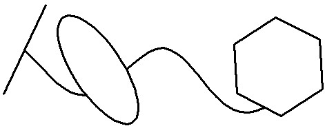
One option for setting the constraint is to create it by three points, or by two segments and a point. The points can be any characteristic points of the lines of arcs, splines, circles, ellipses, segments.
Icon / Keyboard |
Ribbon |
|---|---|
|
Constraints → Middle |
When defining symmetry constraints on three points, we define the following interrelations. The first given point P1 and the second given point P2 define a segment through which the straight line passes through the normal to the segment. A third point P3 will lie on this line. All the constructions in the figure are an explanation of the principle of setting Middle constraint at three points. When creating a constraint, these constructions are not shown. |
|
Another option for setting a constraint is by two segments and a point.
The first given segment L1 and the second given segment L2 determine the direction of the straight lines, which form an angle when crossing. If we draw a bisector from the corner, then the point P3 must always lie on it. It can be explained otherwise. If perpendiculars are dropped from point P3 to segments L1 and L2, then the resulting segments will be equal. The second explanation is also true in the case when the segments are parallel. All additional constructions in the figure are an explanation of the principle of setting Middle constraint over two segments and a point. When creating a constraint, these constructions are not shown. |
|
Examples
Two Lines Perpendicular to each other with Intersection in the Middle.
Let two arbitrary segments be given. Let's make so that their point of intersection is in the middle for each of them. First, we fix the length of the segments by the constraint Fixed length. Next, in the ribbon, select the constraint Middle and with the help of ![]() select the two extreme points of the first segment and the point of the middle of the second.
select the two extreme points of the first segment and the point of the middle of the second.
We finish the entry of constraint objects with the help of ![]() or <Ctrl + Enter>. The second segment is moved so that the point of its middle lies on the perpendicular from the middle of the first segment. Next to the midpoint of the second segment, an icon appears on the symmetry constraint. Similarly, we create the second symmetry constraint: with the help of
or <Ctrl + Enter>. The second segment is moved so that the point of its middle lies on the perpendicular from the middle of the first segment. Next to the midpoint of the second segment, an icon appears on the symmetry constraint. Similarly, we create the second symmetry constraint: with the help of ![]() we choose two extreme points of the second segment and a point of the middle of the first segment, then we finish creating the constraint. The first segment is moved so that the point of its middle lies on the straight line normal to the second segment, and passing through the center of the second segment. Next to the midpoint of the first segment, an icon appears on the symmetry constraint.
we choose two extreme points of the second segment and a point of the middle of the first segment, then we finish creating the constraint. The first segment is moved so that the point of its middle lies on the straight line normal to the second segment, and passing through the center of the second segment. Next to the midpoint of the first segment, an icon appears on the symmetry constraint.
Now it is necessary to make the segments perpendicular. To do this, we use Perpendicularity constraint. The segments moved in such a way that they became perpendicular to each other, and due to two Midpoint constraints the intersection point divides each of the segments in half.
The Axis sets the Midpoint between the Two Segments.
Let three segments be given. One of the segments is an axis and is made of the appropriate type of graphic line. We position the segments vertically using Verticality constraint (select the constraint and with the help of ![]() and specify three segments). Then we make them of equal length using the Equal length constraint. Let us make the segments at the same height with the help of the Horizontal alignment constraint (choose the lower points of the segments with the help of
and specify three segments). Then we make them of equal length using the Equal length constraint. Let us make the segments at the same height with the help of the Horizontal alignment constraint (choose the lower points of the segments with the help of ![]() ).
).
Then we select the constraint Symmetry in the Ribbon, with the help of ![]() we specify two segments and a point on the segment made by the axial line. Finish input with
we specify two segments and a point on the segment made by the axial line. Finish input with ![]() or <Ctrl + Enter>. An icon of the middle appears next to the point on the axial line segment.
or <Ctrl + Enter>. An icon of the middle appears next to the point on the axial line segment.

When editing, the segments, due to constraints, will always remain the same length, at the same height, always vertical, and the segment of the axis will always be in the middle.

The constraint allows you to rearrange one line (or point) of the sketch so that its positioning in the drawing (or plane) and its curvature are a symmetrical reflection of the positioning and curvature of the other line (or point) of the sketch relative to the segment. In other words, if you select two lines of the sketch, and then a line, then the two lines of the sketch will be symmetrically distant, inclined or bent relative to the line, while the symmetry of the lines will be interdependent. Moving any of the lines, changing its curvature, as well as moving and rotating the segment that defines the line of symmetry, will lead to a corresponding rebuilding of another line, or segment defining the axis of symmetry.
Icon / Keyboard |
Ribbon |
|---|---|
|
Constraints → Symmetry |
Symmetrically displays the position, angle and curvature of the sketch line. The length of the line is determined by the characteristic points. For feature points, you can also set Symmetry constraint.
In this case, symmetry can be assigned only to identical constructions: an ellipse is symmetric to an ellipse, a segment to a segment, a point to a point, a spline to a spline.
You can make an arc and a circle symmetrical. In this case, the curvature of the arc and the circle and the position of their centers will be displayed symmetrically.
In order for splines to be symmetric - they should have the same number of characteristic points, the same type of parameterization, they should not have special properties of the derivative at a point, and they should be splines of the same type.
A Symmetric constraint can be created automatically by running the Copy with Symmetry command. To do this, when executing the Copy with Symmetry command, select the Create copies with constraints mode in the automenu.
|
<Ctrl+F> |
Create copies with constraints |
Example
Two Arcs Symmetry
Let us be given two arcs and a vertical segment. We select Symmetry constraint in the Ribbon and, with the help of ![]() , we first select two arcs and then a segment that will define the axis of symmetry. We finish the entry of constraint objects with the help of
, we first select two arcs and then a segment that will define the axis of symmetry. We finish the entry of constraint objects with the help of ![]() or <Ctrl + Enter>.
or <Ctrl + Enter>.
|
|
As you can see the constraint created, the corresponding icons appeared, the radius of the circles and the position of their centers became symmetrical with respect to the segment, but the lengths of the arcs and the position of characteristic points bounding the arcs are not the same.
Create two more Symmetry constraints: for each pair of characteristic points of arcs. In the mode of selection of objects of constraints, we choose the characteristic points of the arcs nearest to the segment and then the segment itself to determine the axis of symmetry using ![]() . When the creation of the constraint is finished, one can see that the near end points of the arcs have become symmetrical with respect to the segment.
. When the creation of the constraint is finished, one can see that the near end points of the arcs have become symmetrical with respect to the segment.
Similarly for points farthest from the segment. Now both the bounding points of the arcs and the arcs themselves are symmetric with respect to the segment. Any movement of the segment will affect the position of the arcs and their characteristic points. Editing the position of characteristic points of one arc will affect the position of points of another. The radii of the arcs are also interconnected.
In order to fully define the drawing, you should create dimensional constraints in addition to the geometric constraints. The driving dimension is responsible for the formation of geometry, therefore, as it changes, the geometry of the line, on which the dimension is created, changes.
To create a driving dimension, you need to use the standard Dimension (<D>) command, but before that, enable the Driving Dimension constraints mode.
Icon / Keyboard |
Ribbon |
|---|---|
|
Constraints → Driving Dimensions; Appearance → Dimension |
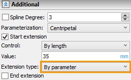
If the dimension is set in the Driving dimension mode, then when creating it, you will be prompted to enter a dimension value. To do this, the Edit dimension value on creation option should be active in the dimension parameters.
Each dimension can be set driving after it has been delivered. To do this, press |
|
Through the context menu, you can also go to edit the value of the driving dimension - the string "Set value". In addition, you can click on the dimension In the dimension value field, you can specify a variable or expression. If the dimension was not created as driving, but the user changed its value, then the dimension automatically becomes driving. For this, Set "Driving" parameter when editing option is enabled. The fact that dimension has become driving is easy to understand by its background, since unlike normal dimensions, the values of the driving dimensions are highlighted in the background. The background color shows the different states of dimension and geometry as a whole. |
|
●Yellow background - the drawing is not defined and has degrees of freedom
●Green background - the drawing is defined, there are no degrees of freedom. When drawing creation is finished, it is recommended that the system is defined.
●Red background - the drawing is over defined, i.e. there are dimensions or constraints duplicating or conflicting each other. The other reason is that there is an error in setting the value of the driving dimension, when the entered value cannot be provided due to other constraint.
Dimensions can be created automatically when creating a sketch.
If the sketch mode (<SK>) in the bindings panel is on, click ![]() on the icon
on the icon ![]() , then dimensions will be created automatically. If you enable the input of driving dimensions
, then dimensions will be created automatically. If you enable the input of driving dimensions ![]() simultaneously with the automatic creation of dimensions, then all the created dimensions will be driving.
simultaneously with the automatic creation of dimensions, then all the created dimensions will be driving.
You can customize the type of automatically created dimensions in the Options command in the “Constraints and dimensions” section, in the “Create Dimensions Automatically” options group. It is convenient to call the section “Constraints and dimensions” through the Ribbon, using icon ![]() Constraints and Dimensions Settings.
Constraints and Dimensions Settings.
Example
Undefined, Defined and Over Defined Drawings
A defined drawing is a drawing with no degrees of freedom and no conflicting dimensions and constraints. In general, when constructing a sketch, you should strive to ensure that the drawing is defined. It is possible to understand that a drawing is defined if when Show under defined lines option is enabled there are no lines highlighted, the number of degrees of freedom in the constraint property menu will be zero, and the background dimensions (if any dimension is created) will be green.
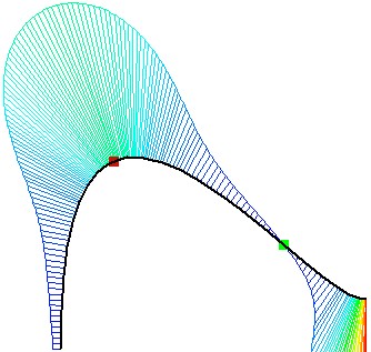
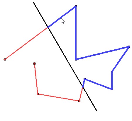
The drawing is shown on the figure. There are no constraints and driving dimensions, i.e. a drawing is a collection of unrelated lines. With the help of constraints and driving dimensions we will make the drawing parametric and fully defined.
The drawing has 20 degrees of freedom. The number of degrees of freedom of the drawing is displayed in the properties window of the constraints. Let's make a Tangent constraint between all segments, tangent to a circle and an arc.
The number of degrees of freedom decreased to 16. Next, connect all the end points of the successive lines of the drawing to each other by the Coincidence constraint. For segments tangent to a circle, the coincidence will be between the end points of the segments and the circle line, but not between the points. After the creation of new constraints, the number of degrees of freedom was reduced to 8.
Next, we assign the constraints Verticality and Horizontality to vertical and horizontal segments, respectively: number of degrees of freedom is 6.

The constraints set the interrelations of the sketch lines and the characteristic position of the lines. Specific dimensions of the drawing will be set using driving dimensions. In the Ribbon, with the help of ![]() , press the icon
, press the icon ![]() and call the command for dimensions creation <D>. Set the dimension of the diameter of the circle and the radius of rounding: the number of degrees of freedom has become 4. The background color of dimension value is yellow - which, like the presence of degrees of freedom, indicates that the drawing has not yet been defined.
and call the command for dimensions creation <D>. Set the dimension of the diameter of the circle and the radius of rounding: the number of degrees of freedom has become 4. The background color of dimension value is yellow - which, like the presence of degrees of freedom, indicates that the drawing has not yet been defined.
Next, we put the linear driving dimension, which sets the position of the circle, and the angular, which sets the slope of the segment. The number of degrees of freedom has decreased to 2, and the background of dimensions values is still yellow.

Use the option Show Under Defined lines: all drawing lines are highlighted. This means that for all the lines of the drawing 2 degrees of freedom are available - moving vertically and horizontally. The sketch itself is already defined by constraints and dimensions so that it cannot change its geometry, but relative to the origin of coordinates, its position is not specified. The position of the sketch can be determined either by specifying two linear dimensions from the origin of coordinates, or by fixing any point. Fix a point using Fix constraint.

After creating a fixation constraint, the background under the driving dimensions became green, and the number of degrees of freedom became zero. This means that the drawing is defined.
If we fix one more point (in general, if we create one more constraint) or put another driving dimension, then the drawing will be over defined. The background under the dimensions will turn red and messages will appear that the constraints are recalculated with errors, since they will begin to duplicate and conflict each other.
Allows you to automatically create the most obvious and simple constraints when creating a drawing. The mode of Infer Constraints when working with a 2D part is disabled by default, when working with a 3D part, on work planes, it is turned on by default. You can enable and disable automatic constraints creation is performed using ![]() icon on the bindings toolbar.
icon on the bindings toolbar.
Icon / Keyboard |
Bindings Toolbar |
|---|---|
|
Infer Constraints |
The types of automatically created constraints can be set by calling the Options in the "Constraints and Dimensions" section in the "Infer Constraints" options group. It is convenient to call the section “Constraints and dimensions” using Ribbon, using icon ![]() Constraints and Dimensions Settings. By default, the constraints Horizontality and Verticality, Coincident, Tangent and Perpendicular are automatically created. If any line is drawn tangentially to another, then a touch constraint is automatically created, if the end point of one line coincides with a point of another line or with the line itself - then a coincidence constraint is automatically created, Verticality and Horizontality constraints will be automatically created for all vertical and horizontal segments. The constraint of perpendicularity is created on all perpendicular segments, except for the case when these segments are horizontal and vertical, since horizontal and vertical segments are already perpendicular to each other due to constraints of verticality and horizontal position.
Constraints and Dimensions Settings. By default, the constraints Horizontality and Verticality, Coincident, Tangent and Perpendicular are automatically created. If any line is drawn tangentially to another, then a touch constraint is automatically created, if the end point of one line coincides with a point of another line or with the line itself - then a coincidence constraint is automatically created, Verticality and Horizontality constraints will be automatically created for all vertical and horizontal segments. The constraint of perpendicularity is created on all perpendicular segments, except for the case when these segments are horizontal and vertical, since horizontal and vertical segments are already perpendicular to each other due to constraints of verticality and horizontal position.
Example
Consider the same drawing as in the example of the previous subsection “Driving Dimensions”. In the previous example, the constraints on the lines were created by the user. In fact, it is faster and easier to make constraints for such a drawing in automatic mode. To do this, after calling the command SK: Sketch , before starting drawing on the panel of bindings we turn on the mode of Infer Constraints ![]() <Ctrl + F2>. Next, using the sketch options, create a drawing.
<Ctrl + F2>. Next, using the sketch options, create a drawing.
Create a circle, then create segments: automatically creates a Tangent constraint for a segment tangent to a circle, for it, since the segment is located vertically, a Verticality constraint is created. For the next, the Horizontality constraint is automatically created. For the third segment, since it is also tangent to the circle - the constraint Tangent is created. For all points that coincide with other points or lines, Coincidence constraint is automatically created.
We create a fillet using Fillet command: Four constraints are automatically created: two tangency and two coincidence. When using the Fillet command, the Trim source curves option was turned on, as a result, on the continuation of the trimmed segments, there remained their intersection point at which the coincidence constraint was set. This constraint is not duplicating, since if the trim option was not enabled, it would define the length of the segments before they intersect. But for this sketch, neither the point nor the constraint itself is needed, so they can be removed.
Thus, using the automatic creation of constraints, a parametric sketch was created without the direct participation of the user in the creation of the parameterization. Further, using driving dimensions, it is possible to specify the dimensions of a parametric drawing, thereby eliminating the uncertainty of the constructions. Regarding the origin, the sketch will be determined by the constraint Fix created for the center point of the circle.
Find and Infer Constraints (Automatic Creation of Parametric Sketch when Construction is Completed)
If the sketch was created when the Infer Constraints is turned off, but you need to make the sketch parametric, then you do not have to create all the constraints manually — use the Find and Infer Constraints command. This command allows you to create not only constraints, but also driving dimensions, in other words, automatically create a parametric sketch. The logic of the automatic creation of constraints and constraints includes algorithms that exclude cases when the drawing is over defined during automatic parameterization.
Icon / Keyboard |
Ribbon |
|---|---|
|
Constraints → Find and Infer Constraints |
To automatically create constraints and driving dimensions on an existing sketch, select the Find and Infer Constraints command in the Ribbon using ![]() , then select lines in the drawing using
, then select lines in the drawing using ![]() for the constraint creation. Holding
for the constraint creation. Holding ![]() can select a group of lines at once by moving the cursor. Moving the cursor from right to left - all lines which touched by the area under the cursor will be selected, moving the cursor from left to right - only those elements that completely fell into the area under the cursor will be selected. You can select all the lines by clicking the icon
can select a group of lines at once by moving the cursor. Moving the cursor from right to left - all lines which touched by the area under the cursor will be selected, moving the cursor from left to right - only those elements that completely fell into the area under the cursor will be selected. You can select all the lines by clicking the icon ![]() (or the <*> key).
(or the <*> key).
|
|
In the command properties window, you can customize the types of constraints and driving dimensions that are created, by setting or clearing the flag opposite the name of a particular constraint or driving dimension. It is possible, by removing the flag in the appropriate field, to cancel the creation of driving dimensions or constraints, if it is necessary, for example, to create only constraints or driving dimensions. For dimensions, Auxiliary option is available - then the created driving dimensions will not be visible when printing the drawing. From Zero Point option creates additional driving dimensions for defining of lines position according to the origin. The up ![]() and down
and down ![]() icons determine the direction for creating driving dimensions relative to the lines: You can create the dimension above or below.
icons determine the direction for creating driving dimensions relative to the lines: You can create the dimension above or below.
The command properties window also displays the total number of degrees of freedom for the lines in the drawing, and the Show Under Defined lines option is available. After the drawing lines have been selected, the options for creating driving dimensions and constraints are adjusted - we complete the input using ![]() or <Ctrl + Enter>. The principle of creating automatic constraints in a drawing is similar to Infer Constraints command.
or <Ctrl + Enter>. The principle of creating automatic constraints in a drawing is similar to Infer Constraints command.
Example
Automatic Parameterization of Sketch After Construction
Consider an example from the previous subsections "Driving Dimensions" and "Infer Constraints". Suppose the sketch has already been constructed, but so far there are no constraints on it. Call the Find and Infer Constraints option. In the command properties window, the current number of degrees of freedom of the sketch is 20. We first cancel the creation of driving dimensions and leave only the creation of constraints. Next, click the icon ![]() to select all the lines, and click the icon
to select all the lines, and click the icon ![]() to complete the command or <Ctrl + Enter>. Eleven constraints were created automatically - information on automatically created constraints and dimensions is displayed in a special message after the completion of Find and Infer Constraints command. Auto-created constraints set the connection of all graphic lines. Five tangencies created: 2 coincidence of the circle and the extreme points of the segments, 2 coincidence of the extreme points of the arc and the extreme points of the segments and 1 coincidence of the extreme points of the segments. Thus, all successive lines are parametrically interconnected. Four tangencies created: Two tangencies between a circle and segments and 2 tangencies between an arc and segments. One Verticality constraint is created for vertical section and one Horizontality constraint for horizontal section.
to complete the command or <Ctrl + Enter>. Eleven constraints were created automatically - information on automatically created constraints and dimensions is displayed in a special message after the completion of Find and Infer Constraints command. Auto-created constraints set the connection of all graphic lines. Five tangencies created: 2 coincidence of the circle and the extreme points of the segments, 2 coincidence of the extreme points of the arc and the extreme points of the segments and 1 coincidence of the extreme points of the segments. Thus, all successive lines are parametrically interconnected. Four tangencies created: Two tangencies between a circle and segments and 2 tangencies between an arc and segments. One Verticality constraint is created for vertical section and one Horizontality constraint for horizontal section.
|
|
|
|
Again, go to the command Find and Infer Constraints. In the properties window of the command, you can see that, after creating constraints, the degrees of freedom of the drawing were reduced to 6. Let us create automatic dimensions. Since we have already created the constraints, then we will remove the flag for creating constraints, and we will set the flag for creating driving dimensions. Add another flag for creating dimensions from zero, i.e. from the origin - this will allow you to completely determine the drawing. Again, select all the lines ![]() , and press the icon
, and press the icon ![]() to complete the command or <Ctrl + Enter>. The message window displays information about the created dimensions and constraints. Close the window. The driving dimensions were automatically created, which established a clear interrelation of all lines of the drawing, taking into account the constraints, and the specified driving dimensions from the origin were also created. The automatically created driving dimensions completely determined the drawing, which is visible due to the green background under the dimension values. It should be noted that it is not necessary to create constraints and driving dimensions separately — it is more convenient and faster to do this at the same time.
to complete the command or <Ctrl + Enter>. The message window displays information about the created dimensions and constraints. Close the window. The driving dimensions were automatically created, which established a clear interrelation of all lines of the drawing, taking into account the constraints, and the specified driving dimensions from the origin were also created. The automatically created driving dimensions completely determined the drawing, which is visible due to the green background under the dimension values. It should be noted that it is not necessary to create constraints and driving dimensions separately — it is more convenient and faster to do this at the same time.
Special Constraints
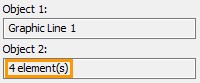
This type of constraint is created only in the automatic mode when creating a sketch, i.e. when the option ![]() is enabled, for certain commands of the graphic lines: Polygon, Offset Curve, Linear Array, Circular Array.
is enabled, for certain commands of the graphic lines: Polygon, Offset Curve, Linear Array, Circular Array.
If the specified commands were not executed in the Infer Constraints ![]() mode, then, using the Find and Infer Constraints command, it will not be possible to create special constraints — the usual constraints will be created (from the list of possible ones) for the Find and Infer Constraints command.
mode, then, using the Find and Infer Constraints command, it will not be possible to create special constraints — the usual constraints will be created (from the list of possible ones) for the Find and Infer Constraints command.
This constraint is automatically created if the polygon is constructed by Polygon sketch command (<SK> → <Shift + R>). The drawing is indicated by an icon ![]() . Due to this constraint, when editing and parameterizing its lines and characteristic points, a polygon behaves as a single whole, preserving the equality of sides and angles.
. Due to this constraint, when editing and parameterizing its lines and characteristic points, a polygon behaves as a single whole, preserving the equality of sides and angles.
Example
Driving Dimension of the Polygon with Polygon Constraint
Construct a polygon in the automatic mode of creating constraints. Call the Sketch command (<SK>), turn on the Infer Constraints (<Ctrl + F2>) mode, select the Polygon command (<Shift + R>). In the properties of the polygon command, specify the number of sides equal to 5. Using cursor, we change the radius of the inscribed (or circumscribed) circle, with the help of ![]() we specify the position of the characteristic point defining the polygon. As the point is selected, Polygon constraint is created. The constraint icon appears near the central point, and the constraint can be seen in the “Model Elements” window.
we specify the position of the characteristic point defining the polygon. As the point is selected, Polygon constraint is created. The constraint icon appears near the central point, and the constraint can be seen in the “Model Elements” window.
Using the Fix constraint, we fix the position of the center point of the polygon, and set the driving dimension to any dimension of the polygon.

Changing the value of the driving dimension, you can see that despite the fact that it only sets the distance between the two extreme points of the polygon segments, the geometry of the polygon changes completely, maintaining the equality of the sides and angles.
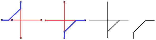
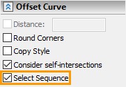
This constraint is automatically created if you construct an offset curve (Offset Curve <SK> → <Ctrl + J>). The drawing is indicated by an icon ![]() . Due to this constraint, the offset curve, consisting of segments and arcs, behaves like a single line during parameterization and editing. The offset curve can be constructed for source lines with constraints and for lines without constraints.
. Due to this constraint, the offset curve, consisting of segments and arcs, behaves like a single line during parameterization and editing. The offset curve can be constructed for source lines with constraints and for lines without constraints.
Example
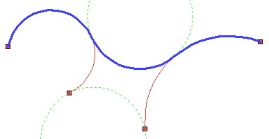
Tangency of Offset Curve and Fixed Segment
A sequence of segments and arcs is constructed in the mode of continuous input of lines. Call the Sketch command (<SK>), turn on the Infer Constraints (<Ctrl + F2>) mode, select the Offset Curve command (Ctrl + J>). With the help of ![]() choose a sequence of lines, and with the help of
choose a sequence of lines, and with the help of ![]() choose the position of the offset curve. As soon as the position of the offset curve was determined, the Offset constraint was automatically created.
choose the position of the offset curve. As soon as the position of the offset curve was determined, the Offset constraint was automatically created.
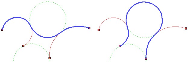
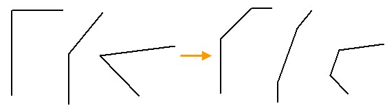
Add a horizontal segment to the drawing and fix it with a constraint Full Fix. Also add a full fixation to all lines of the original sequence. Then, using the Tangent constraint, we define a constraint between the segment and the arc of the offset curve.

The offset curve moved as a single line, maintaining an equal distance from the original sequence of lines. The arc of the offset curve became tangent to the segment.
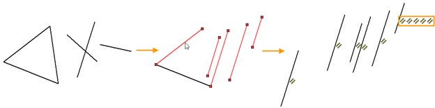
This constraint is automatically created for a linear array (Linear array <XL>). It is indicated in the drawing by an icon ![]() . Due to the constraint, the drawing lines created by the array, during parameterization and editing, retain the relations that was set by the linear array: equal pitch and alignment on a single line. To create this constraint, the copy mode option of the automenu of an array command should be specified as Create copies with constraints.
. Due to the constraint, the drawing lines created by the array, during parameterization and editing, retain the relations that was set by the linear array: equal pitch and alignment on a single line. To create this constraint, the copy mode option of the automenu of an array command should be specified as Create copies with constraints.
|
<Ctrl+F> |
Create copies with constraints |
Example
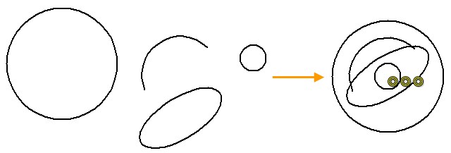
Constraints and Driving Dimensions on the Linear Array Elements with Linear Array Constraint
Suppose we are given a rectangle (built with constraints and with a fixed point), on the left side of which there is a circle. Using the Linear array command, copy 5 circles inside the rectangle. We check that the Infer Constraints mode is enabled in the sketch, then through the context menu, by clicking ![]() on the circle, we call the Linear array command. Check that the Create copies with constraints mode is active.
on the circle, we call the Linear array command. Check that the Create copies with constraints mode is active.

Specify the number of copies to 5, choose the starting point of the array, direction and step (for more information on creating arrays, see the section “Moving and Copying Drawing Elements. Arrays. Use of Clipboard" in subsection "Linear array"). As soon as the array was built, a Linear array constraint was automatically created. A constraint icon ![]() has appeared on the drawing.
has appeared on the drawing.

Fix the length of the left side of the rectangle, and position the horizontal of the array in the middle of the rectangle using the Middle constraints. And also change the array pitch by setting the driving dimension.

Choosing the constraint Middle with the help of ![]() we specify the upper segment of the rectangle, then the lower one, and then the center point of any circle, for example, the first one. After entering the constraint objects and completing the command, all the elements of the array, according to the Linear array constraint, were moved as a whole.
we specify the upper segment of the rectangle, then the lower one, and then the center point of any circle, for example, the first one. After entering the constraint objects and completing the command, all the elements of the array, according to the Linear array constraint, were moved as a whole.
To change the array pitch, you can put a driving dimension between any points of two circles. For example, put the dimension between the centers of the third and fourth circles. By changing the dimension value, the user also changes the step for all elements of the array, since all array elements are bound by a Linear array constraint.
This constraint is automatically created for a circular array (Circular array <XR>). In the drawing and in the “Model Elements” window it is indicated by the icon ![]() . Due to the constraint, the lines in the array retain the interrelations during parameterization and editing: equal angle between the elements of the array, equal radius from a single point of the center of the array. To create this constraint, the copy mode option of the automenu of an array command should be specified as Create copies with constraints.
. Due to the constraint, the lines in the array retain the interrelations during parameterization and editing: equal angle between the elements of the array, equal radius from a single point of the center of the array. To create this constraint, the copy mode option of the automenu of an array command should be specified as Create copies with constraints.
|
<Ctrl+F> |
Create copies with constraints |
Example
Circular Array with Constraint upon Editing
Let us be given a circle on the same axis of which a rectangle is constructed, the center of the rectangle lies on the axis. All constructions are created in the Auto Parameterization mode. Create a circular array of a rectangle. We check that the Infer Constraints mode is turned on in the sketch, select the area above the rectangle with pressed ![]() , then click
, then click ![]() on the highlighted rectangle through the context menu and call the Circular array command. Check that the Create copies with constraints mode is active. Specify the number of copies equal to 4, choose the center point of the array and the angle. As soon as the array was created, a Circular array constraint was automatically created. A constraint icon
on the highlighted rectangle through the context menu and call the Circular array command. Check that the Create copies with constraints mode is active. Specify the number of copies equal to 4, choose the center point of the array and the angle. As soon as the array was created, a Circular array constraint was automatically created. A constraint icon ![]() has appeared on the drawing.
has appeared on the drawing.
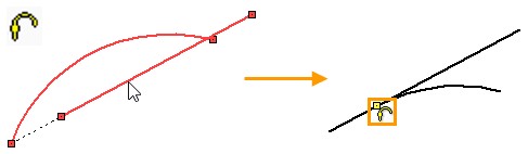
We put several driving dimensions on the elements of the array and change their values. Due to the Circular array constraint, all elements have changed, maintaining the equality of the geometric dimensions.
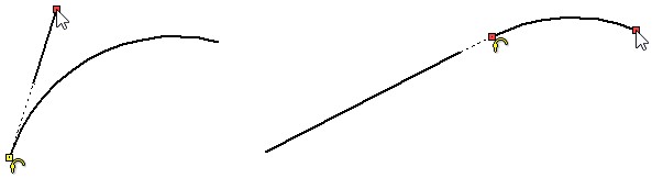
Smoothness
This restriction is automatically created when the command of the spline smoothness is executed. In the drawing and in the “Model Elements” window, the constraint is indicated by icons ![]() (G1 Continuity) or
(G1 Continuity) or ![]() (G2 Continuity), in accordance with the name of the created smoothness. These constraints allow you to maintain smoothness between a spline and another curve (including another spline) when editing a spline or a curve.
(G2 Continuity), in accordance with the name of the created smoothness. These constraints allow you to maintain smoothness between a spline and another curve (including another spline) when editing a spline or a curve.
Example
Spline with smoothness limitations
In Infer Constrains mode, create an arc to the left of the spline, and another spline to the right of the spline. Two Coincident restrictions were automatically created. Let us create the smoothness of G1 for the extreme left point of the spline, and the smoothness of G2 for the extreme right point. Two constraints of G1 Continuity and G2 Continuity were created automatically. Now when editing sketch lines, the conditions defined by smoothness will always be met.
|
|
See also: Sketch