3D Axis


3D Axis |
|
The command creates 3D axes on the basis of rotation surfaces and edges. Axes created in such a way preserves associative links with the initial elements.
General Information and Opportunities
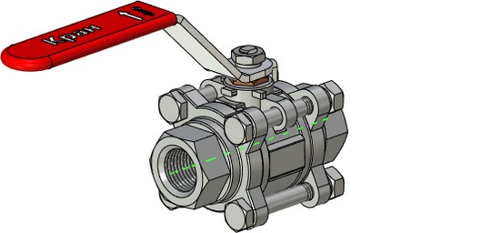
This command allows you to create straight axes on the basis of surfaces of rotation (cylindrical, conical, toroidal), as well as circular edges. As additional elements for specifying the dimensions of the created axis, you can select any other model elements.
The 3D axis object may be used in the following ways:
●You can use it as a rotation axis or direction element when creating various operations (extrusion, rotation, array, etc.);
●You can use it as an object for setting 3D dimensions (between axes, from axis to plane, edge, etc.).
Any 3D path or track can be converted into a 3D axis object using the Convert to Axis command of the context menu or enabling the corresponding parameter in the parameters dialog box.
|
|
3D axis is automatically created based on the center graphic lines or sketch lines of work planes and projections.
|
|
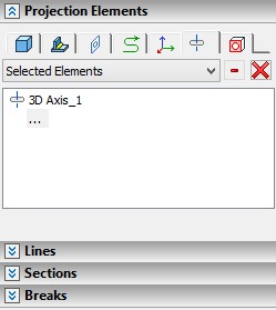
Also, the 3D axis can be used as an object to project. See the “2D Projections”.
3D Axis Creation
Use the 3PX: Create 3D axis command to create a 3D axis:
Icon |
Ribbon |
|---|---|
|
3D Model → Constructions → 3D Axis |
Keyboard |
Textual Menu |
<3PX> |
Construct > 3D Axis |
You can select the element for a 3D axis creation using the automenu:
|
<M> |
Main element |
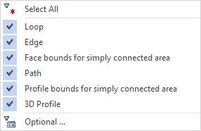
This option becomes active immediately upon entering the command. It contains a list of 3D element selection filters. The elements can be used as the basis for a 3D axis creation. You should pay attention to the active filters when selecting elements. For more information about working with these filters, see the chapter “Basic 3D Terms and Concepts of Modeling with T FLEX CAD”.
To select the main element you should point the cursor to the required object. The object will be highlighted and the hint with the element name will appear. You should press The selection of the main item is canceled by clicking the Clear Perpendiculars dropped from the extreme points of the selected element on the axis are used as limits of the 3D axis. If you select a round edge as a main element, a 3D axis of zero length will be created. The 3D axis will be extended from the both sides according to the Overhang parameter value. |
|
To extend a 3D axis from one or both sides, you should select additional elements. The elements will define the length of the axis. Use the following option for this purpose:
|
<G> |
Additional Elements |
The selected elements will be automatically added to the corresponding list in the properties window. Use the following buttons to edit the elements list: Collapse In this case, the perpendiculars dropped from the extreme points of the additional elements to the axis will be used as limits. In this case, the perpendiculars will be the limits of the 3D axis, dropped from the extreme points of the additional elements on the axis, taking into account the value of the Departure parameter. The Overhang parameter is also considered. |
|
By default the Overhang parameter units are millimeters. You can change units by clicking on the corresponding units icon.