Route


Route |
|
The route is a special type of a 3D path, that is composed of straight segments. The adjacent straight segments are connected by arcs of a specified radius. This type of a 3D path is mostly intended for defining a spatial trajectory used for creating pipelines.
Basic Information and Features
Sections of the route
The system allows you to create a route consisting of several sections constructed by various methods:
●by specified points;
●using the geometry of already existing objects (elements of wire geometry, elements of bodies).
When constructing the route by specified points for each new point in the scene, the LCS manipulator appears. The manipulator allows you to set its position in absolute coordinates or relative to the selected binding (3D node, vertex, etc.). By default, the direction of the axes of the manipulator coincides with the direction of the axes of the global coordinate system. |
|
Manipulator provides for the following transformations:
●translation along the axis (X, Y, Z). To enable translation, move the cursor closer to the axis arrow.
●translation in the plane (XY, XZ, YZ). To enable translation, move the cursor closer to the image of the plane.
●translation by three axes. To enable translation, move the cursor closer to the sphere at the center of the manipulator.
●rotation about the axis (X, Y, Z). To enable rotation move cursor closer to the arc (the color of the arc corresponds to the color of the axis around which the rotation will be carried out).
Manipulator can work in one of the two modes:
●numeric specification of the transformation value. To work in this mode move the cursor of the mouse closer to the manipulator (it will be highlighted and the tip will appear on the screen) and translate the mouse with the pressed left button. Precise value of the transformation can be specified on the system toolbar.
![]()

●transformation is prescribed by snapping to the existing object of the model (for example, translation up to a 3D node). To work in this mode move the cursor of the mouse closer to the manipulator and click ![]() . After that the object snapping will be working upon translation of the cursor. In this way it is possible to specify the translation up to a point, edge midpoint, etc.
. After that the object snapping will be working upon translation of the cursor. In this way it is possible to specify the translation up to a point, edge midpoint, etc.
![]()

Any change in the location of the manipulator is reflected in the auxiliary window Transformations. For each point of the path a separate list of transformations is saved. Translations along the axes are summed up. Transformations with the use of object snapping are recorded as a separate line. Transformation selected in the list can be deleted. The object snapping can be redefined by indicating a new object in 3D scene. The order of transformations can be changed by moving transformation up and down along the list with the help of buttons with arrows. However, it is important to take into account the fact that an arbitrary change of the order might lead to the incorrect result. |
|
There is the possibility of multiple editing of points. The selection of the required points is carried out in the corresponding list in the properties window. After this translation of the manipulator will affect the position of all selected points.
|
|
|
|
|
For a section of the route built at specified points, a type can be specified, which determines the method of its construction:
●Spline through points;
●Spline by Polygon;
●Polyline.
Spline through points
It is a spline that passes through all given points. The minimum degree of such a spline (the degree of the polynomials by which it is described) is 3.

The adjustment of the spline in terms of the behavior between adjacent specified points is determined by the maximum deviation of its shape from the chord between these points.
|
|
|
|
All default points are spline interpolation points. In the case when the exact passage through the point is not required, but rather only the approximate one, it is necessary to remove the Interpolation Point flag from it and set the maximum deviation value. The deviation of the curve at all points of approximation is the same throughout the route. |
|
|
|
|
|
At each interpolation point, it is allowed to change the smoothness parameters of the curve, setting the direction and values of the first derivatives of the polynomials (Tangent parameter) of the spline. The value of the Tangent parameter is specified by the Tangent to curve at 3D Node arrow. The direction of the tangent is specified by two manipulators in the form of arcs Tangency Direction. |
|
For intermediate spline interpolation points, the system automatically selects the direction and calculates the optimal values of the first derivative, while observing the condition for preserving the smoothness of the curvature (the smoothness of the third derivative of the spline polynomials). However, it is allowed to set different values. It should be remembered that in this case the condition of preservation of tangency (smoothness of the first derivative of polynomials) is violated; accordingly, the curvature at such points will tend to zero.
|
|
|
|
Spline by Polygon
Represents a spline that passes along a controlled polyline, providing the condition for continuity of curvature. A polyline is a set of specified points connected in series by chords. The spline itself does not pass through the points (except for the start and end points). By default, the system builds a spline of the 2 degree. If necessary, you can change the degree of the spline, but the maximum allowable value of the degree of the spline should be one less than the number of specified points.
The main parameter of the given points is the Weight of the curve function. The greater the weight of the function at a point, the closer the curve goes to it.
|
|
|
|
Polyline
It is a spatial polyline consisting of straight line segments, sequentially connecting a set of specified points. This is a special case of a spline by broken line of the 1st degree.
For a polyline, a rounding can be specified with a total value for the entire section or separately for each given point. The rounding dragger is available for any given point of the section except the start and end points. Moving the dragger changes the value of the rounding radius at the selected point. |
|
Segments Based on Geometry of Existing Objects
The construction of sections of the route based on the geometry of existing objects involves the use of the following types of elements:
●Based on paths/edges;
●Based on surfaces/faces.
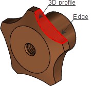
When building a route based on paths or edges, the created section will coincide with them completely. You can change the position of the section, its starting and ending points using the following draggers (the numerical values of the draggers can be set in the properties window).
●Location. Specifies the shift from the ends of the selected object.
![]()
●Offset. Specifies the shift of the segment of the path from the selected object.
![]()

●Starting angle. Specifies the angle of rotation around the selected edge/path. Located at the start point of the path section.
![]()
●Twist angle. Specifies the angle of rotation of the end point with respect to the start point of the path section.
![]()

When creating a route by a set of edges (paths), it is necessary to add a separate section for each of them.
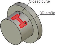
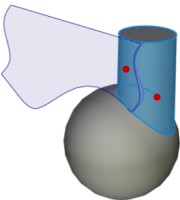
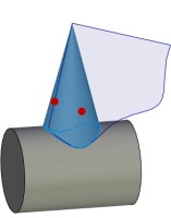
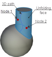
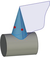
When creating a route based on faces or surfaces, the starting point of the section is created on the surface of the object at the point of the mouse click. After that, after adding a new point, you can move it using the manipulator or by setting the coordinates U, V in the properties window.
![]()
![]()

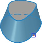
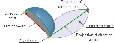
The created curve can be moved along the normal to the surface, and an equidistant to the section lying on the surface is created. It is allowed numerical values in the properties window.
![]()

Despite the difference in construction methods, the areas can be mated with each other, forming a single spatial 3D path. In addition, it is allowed to combine several 3D paths into one, as well as break the existing one into smaller ones.
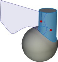
When mating several sections of different types in one route and when several routes join, a transition zone is constructed between sections in the form of an additional curve which is connecting them. Moreover, the smoothness of the first derivative of polynomials is ensured by the equality of the values of the parameters Tangency on Start, Tangency on End of the points being connected. In addition, the system allows you to automatically provide the smoothness of all transition zones, selecting the optimal values of the above parameters for all mating sections by the Create smooth path parameter.
|
|
If a newly created route starts at the extreme point of an already existing route, then the system allows them to be smoothly mated, while at the same time allowing you to change the direction of tangency using the Reverse outer tangent parameter.


When combining the selected section with the following, both of them should be of the same type. The resulting curve will inherit the parameters of the first section.
The section is divided into two sections by the selected point, the route is divided into several routs - by the selected section.
The system allows you to change the direction of the created sections to the opposite.
Using context menu in work with the manipulator
When selecting the manipulators the following commands will become available in the context menu:
●for translation along the axis

●for translation in the plane

●for translation along three axes

●for rotation around the axis

The option of the Settings menu defines the step with which the distance and the angle change upon translations and rotations of the manipulator.

Additional features
For convenience and clarity of work with the command, the system offers a number of options.
●Pipe Diameter. The option allows to dynamically display a preview of the route in the 3D scene by setting the curve thickness (increases convenience when working with a large number of 3D paths in the scene). ●Mark points with curvature less than. Displays diagnostics in the 3D scene about points of the 3D path in which the radius of curvature is less than the specified one. ●Mark breaks. Displays diagnostics in the 3D scene about the points in which the direction of a curve changes in such a way that zero curvature and an infinitely large radius appear. ●Check self-intersections. Displays diagnostics in the 3D scene about the self-intersection points of the 3D path. |
|
Creating of route
To create the route there is a separate command:
Icon |
Ribbon |
|---|---|
|
3D Model → Construct → Route |
Keyboard |
Textual Menu |
<3PP> |
Construction > Route |
The same command is invoked from the pipeline creation command with the help of the option of the automenu:
|
<B> |
Create/edit route |
The Type parameter allows you to assign a routing group to which this route will belong. This allows you to eliminate errors when creating pipelines, when there are several communication groups in the assembly at once. |
|
Creating and editing points
After invoking Route command the first section with the start point is automatically created. This point becomes active. A point is considered active when it is highlighted in the list of points in the properties window. A manipulator of the active point appears in the 3d window.
By default the following option is active in the automenu:
|
<F> |
Select a point |
This option allows you to bind route points to geometric 3D points of the model (3D nodes, vertices, etc.). In this case, the parent geometric object will be displayed in the list of points next to the point name in parentheses. |
|
Deleting a point binding to a geometric object is implemented using the following automenu option:
|
<L> |
Delete linking of Point |
After deleting the link, location of the point is stored in absolute coordinates
The system offers two modes of adding points, the choice between which is done by the auto-menu buttons:
|
<H> |
Add Note at the end of Path |
|
<J> |
Add Note at the beginning of Path |
In the case of adding points before the active point, new points are added to the beginning of the section.
Change the location of the active point by using the manipulator in the 3d window. The absolute coordinates are shown in the properties window. For points of the section by surface fields the U, V, N coordinates are filled in. For points of the section by edge the U, V, R coordinates are filled in. Coordinate values can be changed manually.
When creating or editing a point it is often more convenient to specify the values of the shifts but not their absolute coordinates. For input of this data the group of parameters Offset is used. When creating the new point its location initially coincides with the point created just now. By specifying the value of the shift, we translate the active point with respect to the previous one. If the shifts are specified upon the editing of the point, then the result will be its translation relative to its current location.

If the Offset flag is set for a point, then it is not recommended to bind this point to a geometric object. The point should be free from geometric binding.
Segment points can be specified in the coordinates of an arbitrary LCS. To select\cancel LCS in automenu use options:
|
<C> |
Select LCS |
|
<V> |
Cancel LCS selection |
After selecting a coordinate system, it will be used for the current point and all points that are created after the current one. LCS deselection transfers the coordinates of the current point to the global coordinate system. Section of the path can contain any combination of coordinates definition.

A new point creation is performed using the automenu option:
|
<Enter> |
Finish point Editing and create new Point |
The new point is initially located in the same coordinates as the point created just now.
To delete the active point, you need to use the automenu option:
|
<Del> |
Delete Point from Path |
In the properties window next to the list of points there are the buttons, which also allow us to add the points before ![]() or after
or after ![]() the active point, delete the active point
the active point, delete the active point ![]() , delete link of points
, delete link of points ![]() , split section into two at the active point
, split section into two at the active point ![]() , and import points from external file*.txt and *.csv
, and import points from external file*.txt and *.csv ![]() .
.
Depending on the selected curve type, the corresponding point parameters are activated.
Parameters of points are set in the corresponding tab of the properties window depending on the selected type of the section of the path.
The Rounding parameter allows you to specify the rounding radius of a Polyline type area at a selected point.
The Tangent parameter sets the same value of the first derivative of the polynomials of the curve before and after the selected point. To set different values, disable the Symmetric flag:

The Reverse outer tangent parameter is used to change the direction of one route when smoothly mating with another.
The Tolerance parameter is used for the Spline through points segment type. To set the maximum deviation of a curve from a point, it is necessary to disable the Interpolation Point flag (the other parameters of the point will not be available):

The Weight parameter determines the degree of influence of the selected point on the segment of the Spline by Polygon type.
Creating and Editing Sections
The list of sections of the route is displayed in the corresponding tab of the properties window. To add a new section, use the Add... When deleting a section from the middle of the list, the previous and the following section are connected by a transition zone. The Merge with Next The division of the area is carried out at the selected point using the Split |
|
The parameters Tangency on Start and Tangency on End allow you to provide a smooth conjugation between the transition curve and the mating sections. The option Create smooth path provides automatic smoothing of all transition zones between sections. The option is located in the Options tab of the properties window.
The Reverse Curve Direction parameter allows you to change the direction of the section to the opposite. This is useful when adding new sections to provide the same direction of the curve in all sections of the route.
For a section of the route built on specified points, the type that determines how to build it is selected in the drop-down list on the Sections tab in the properties window. The parameters of the curve section, depending on its type, are set in the corresponding tab of the properties window. The Spline Degree parameter is used for the Spline through points and Spline by Polygon section types. The Radius of Rounding parameter sets the total rounding value for all points of the section of the Polyline type. The Offset parameter sets the value of the movement of the section created by the path/edge and the surface/face, along the normal from the object. The Straighten by Chord parameter allows setting the value of the maximum deviation of the curve shape from the chord between the interpolation points in the corresponding field for a Spline through points type. |
|
|
To create a section based on paths or edges, use the option:
|
<E> |
Create segment by path/edge |
After activating the option, you should specify an object of one of the types:

The selected object will set the trajectory of the created section. The positioning of its starting and ending point is performed with the help of manipulators or by setting the coordinates U, V in the properties window. The R field duplicates the value of the Offset parameter.

To create a section based on faces or surfaces, use the option:
|
<S> |
Create segment by surface/face |
After activating the option, you should specify an object of one of the types:

The start point of the section is created at the place of the mouse click. After that, having added the new point, it can be translated with the help of the manipulator or by specifying coordinates U, V in the properties window. Coordinate N duplicates values of Offset parameter.

Route Editing
To combine the created route with the existing one, use the option:
|
<M> |
Merge two paths |
After activating the option, you should specify the target route to combine with. If the routes do not have common points, a transitional curve will be created between them.
To divide the route into two, use the option:
|
<D> |
Split Path |
The separation of the route is performed from the current section. After separating the path, the transition zone between the sections is deleted, and the system proceeds to editing of the newly created route.
The construction of the route, smoothly mated at the point with the existing one, is performed by setting the Tangency on Start flag and selecting the direction of tangency using the Reverse outer tangent parameter.