Pipeline Creation


Pipeline Creation |
|
Using general methods and steps for creating pipeline routing model described below you may create routing designs of other types as well.
To create a pipeline model you may select Tools >> Routing >> Pipeline >> Pipeline item from the text menu.
Icon |
Ribbon |
|---|---|
|
3D Model → Create → Pipeline |
Keyboard |
Textual Menu |
<3PI> |
Operation > Pipeline |
The operation creates a pipe which will be presented as a solid 3D body. The body will be resulted from sweeping of selected contour along a trajectory (route). The route can be created using one of the commands from the Routing section: Laying Route ![]() or Route
or Route ![]() . It can be also specified as a model edge or any other element that determines wire geometry.
. It can be also specified as a model edge or any other element that determines wire geometry.
The pipe profile shape and dimensions are specified without additional constructions. They are set in the Properties window that appears after the command activation.
More information about the pipeline properties can be found in “Pipeline parameters” section.
You can create a pipe along the whole route or its part.
To define the operation, follow the steps:
1.Select 3D curve defining the trajectory.
2.Select starting 3D point of the pipe (optional).
3.Select ending 3D point of the pipe (optional).
4.Define operation parameters (pipe diameter, wall thickness, etc.).
5.Confirm operation creation.
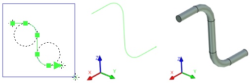
Pipe can be created using one of the two ways:
●In the first approach, the trajectory of the pipe is divided into separate segments – straight lines, circular arcs and splines. A separate body will be constructed for each segment. Depending on the segment type, this can be a cylinder or a torus, or a spline. The resulting operation consists of multiple bodies. If necessary it can be subjected to the 3SD:Divide Solid operation for getting individual bodies – the pipe segments.
●In the second approach, the trajectory is treated as a single path. The pipe profile will be swept along this trajectory. The result is a single body whose surface consists of a set of spline faces and faces of revolution (cylinder, torus). In some cases, system can simplify the resulting body geometry by replacing (wherever possible) spline surfaces with analytical ones (portions of cylinders or tori).
The first approach is used by default. It is faster than the second and reduces overall regeneration time. However, pipe operation created in this way may behave incorrectly under certain operations (for example, when creating 2D projections or in Boolean operations) because it is made of multiple bodies. If this is your case you may apply the second approach (creating the single body pipe), however, the model regeneration time may increase.
Pipeline Command Automenu
Upon calling the command, the following option is activated in the automenu automatically:
|
<T> |
Select trajectory |
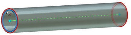
The option allows to define a trajectory (3D curve) for the pipeline being created. When the option is active, you need to select a 3D object that presents wire geometry. The object will define a trajectory for the pipeline.
If trajectory is presented as a 3D path based on 2D elements, then it can be also selected in the 2D window.
The selected 3D curve and its defining elements will highlight.
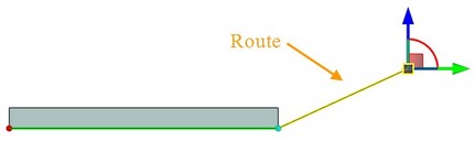
You may use a route as a trajectory. If the route does not exist or existing route must be edited, use option:
|
<B> |
Create/Edit Route |
More information about routes creation can be found in “Route” chapter.
When the route creation is finished press button ![]() . You will return to the pipeline creation command.
. You will return to the pipeline creation command.
The pipeline parameters can be specified in the dialog window called via:
|
<P> |
Set entity parameters |
More information about pipeline parameters is given in “Pipeline parameters” section.
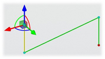
You can define additional 3D points that specify pipeline limits – starting and ending points, using options:
|
<L> |
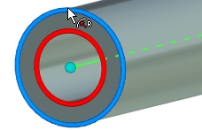
Select starting point for pipe |
|
<M> |
Select ending point for pipe |
The options allow selection of any 3D object that can define a point as a corresponding pipeline end. System creates a “cutting” plane, which is perpendicular to the pipeline routing. This plane becomes a bound of the pipeline.
Pipeline ends cannot be located beyond the selected route.
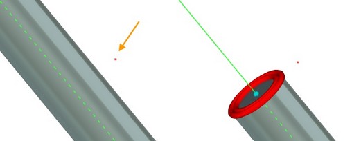
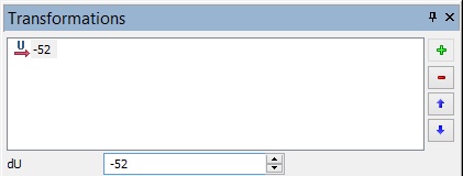
You can edit location of starting and ending points of the pipeline using options:
|
<S> |
Edit start position |
|
<E> |
Edit end position |
Transformations window appears after selection of one of the options. The current location of bounds is displayed there. The value can be changed manually.
You can also define pipeline limits using manipulators. Point the cursor at the pipeline bound manipulator and move it with pressed Current offset value is displayed on the system toolbar.
|
|
To create a pipe insert, operation that modifies pipe for inserting other parts, use option:
|
<O> |
Select operation for pipe insert |
The option allows you to select body for the pipe insert.
Insert allows system to consider the pipeline as a singular object even if there are fittings that divide it into parts. It is necessary for further pipelines quantity and length correct calculation.
The pipe inserts are displayed in Pipe inserts section of the Properties window.
You can cancel source path and end points selection via option:
|
<K> |
Cancel selection of trajectory and end points |
You can use the following option for the standards editing:
|
<G> |
Edit standards list |
The Pipeline Standards window appears after its activation. Parameters of pipeline profile can be specified here according to existing standards.
|
<С> |
Library Configuration |
More information about configurations can be found in “Holes” chapter.
The pipeline creation can be used in combination with the further Boolean operation. For this, you need to select first the type of Boolean operation.
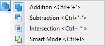
Then select a body using option:
|
<Ctrl+T> |
Select target body for Boolean |
More information about Boolean operations can be found in “Boolean Operation” chapter.
Properties Window
You can specify the following properties in Parameters window:
Pipeline Parameters
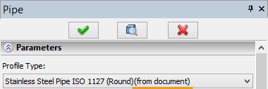
The pipeline profile properties are specified in the Parameters section.
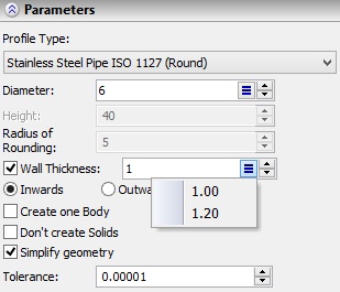
Profile Type. You need to select one of the profile types from the drop-down list: Round, Rectangular, Select Standard. According to the selected profile type, you can specify its dimensions.
Round profile
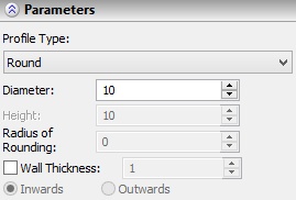
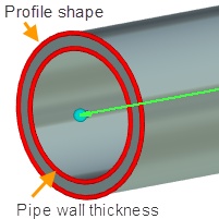
Pipe Diameter. By default, it defines the outer diameter of the pipe. If the switcher is in Outwards mode, the parameter defines inner diameter.
Wall Thickness defines the difference between the outer in the inner diameters of the pipe. By default, the value is put inside the pipe (switcher is in Inwards mode).
You can change pipe diameter and thickness using manipulators in the 3D scene. Current value of the parameter can be set on the system toolbar.
If smooth transition disappears between the two straight pipe segments when creating a pipe, then you must fix correlation between the rounding radius and the pipe diameter.
Rectangular profile
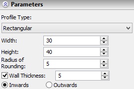
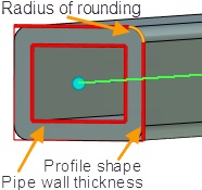
Width, Height, Radius of Rounding specify parameters of outer pipe profile by default. If the switcher is in Outwards mode, the parameter defines inner profile.
Permitted values for Radius of Rounding are from “0” (without rounding) up to half of the minimum dimensions: length or height.
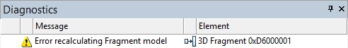
If the radius is not within the value or the rounding cannot be created because of other reasons, the system displays the diagnostic message.
Wall thickness. By default, the value is put inside the pipe (switcher is in Inwards mode).
You can change rectangular profile dimensions using manipulators. Current value of edited parameter can be set on the system toolbar.
Select standard
If the profile type is specified by a standard, values of parameters are defined from the predefined list. All parameters are divided into control and dependent.
Permitted values of a dependent parameter are defined according to the selected value of the control parameter.
For the round profile type, diameter is the control parameter. Dependent parameters are walls thickness, fixation of inside dimension and option for creating one body.
For the rectangular profile type, height and width are the control parameters. Dependent parameters are walls thickness, fixation of inside dimension and blending.
You can manage the standards list using Standards window.
More information about the window can be found in “Standards” section.
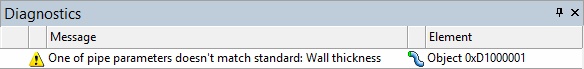
If the specified value of any parameter does not match the standard, when you edit pipe profile defined by a standard, the system will display a diagnostic message.
Common parameter
The following parameters are available for all profile types:
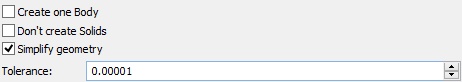
Create one Body. Parameter specifies the way of pipeline creation. When the flag is not set, the first way (separate segments) is used. The resulting operation consists of multiple bodies. When the flag is set, the second way is used – the resulting operation will present a single body.
Don’t create Solids. When the flag is set, the operation will be created but it won’t be displayed in the 3D scene. It is useful in models with large number of pipes.
Simplify geometry. With this parameter set, the geometry of the resulting body will be simplified by replacing (wherever possible) spline surfaces with analytical ones (cylinders or tori).
Tolerance. This parameter defines the accuracy of pipe construction, resulting with particular number of intermediate steps when sweeping pipe profile along the spline trajectory to ensure the required accuracy of surface.
Profile Orientation
It is possible to specify rotation of profile while sweeping using flag Rotate Profile (available only for rectangular profile).
The profile orientation is the full angle of rotation according to the axis directed along the tangent to the path. It is specified at the pipe ends with two parameters-angles:
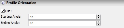
Starting Angle is defined as an angle between Y axes of base LCS and source LCS.
Source LCS - X axis is directed along the tangent to the path, Y axis is defined by the principal normal to the path.
Base LCS – LCS (connector or connection point) which is located on the pipe bound (starting or ending). The X axis is directed along the tangent to the path, the origin merges with the the bound of the pipe (starting or ending).
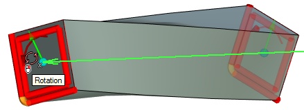
Ending Angle is specified in the Properties window or using manupulator in 3D scene.
When you use manipulator, the current rotation angle is displayed on the system toolbar.
![]()
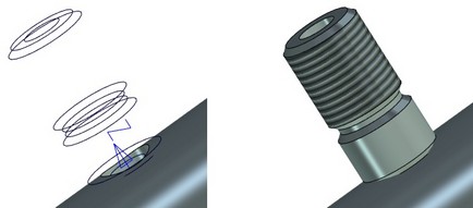
Endings and Connections
There is possibility to set endings and connectors types in the Pipeline command by inserting library fragments into the model. Bevels, flanges, threads and so on can be used as such fragments.
In the 3D Model window such pipeline is displayed as a single object, but physicaly in the model it consists of several fragments (start, middle and end). If you edit any of these fragments the Edit Pipeline command activates automatically.
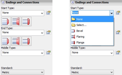
Ending or connection type can be selected either from the quick access drop-down list or by clicking the corresponding icon. If you select type from the list and it is not presented among the icons below, the new icon will replace the last right icon.
Item “Select” in the drop-down list allows you to select element from custom libraries added to selection list.
The content of the selection list is linked with the value of the Standard field and will update accordingly.
The elements of endings and connection are created as adaptive fragments. They are stored in folder “..\Libraries\Routing”. If necessary, library can be supplemented with custom elements.
To define selection from the predefined set of ending and connection elements use “Standard” data field.
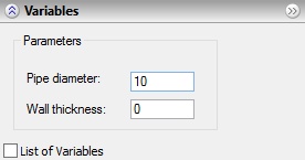
Use button ![]() Edit variables to set external values of fragment variables. The Variables section appears after pressing the button.
Edit variables to set external values of fragment variables. The Variables section appears after pressing the button.
System checks for correctness of endings insertion and displays message if it is impossible to perform the operation. It can happen if, for example, the ending length is greater than the pipeline length.
You can select ending or connection library using option:
|
<B> |
Library configuration |
More information about configurations can be found in “Holes” chapter.
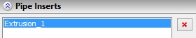
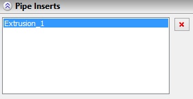
Pipe Inserts
This section of Properties window displays elements, used in option ![]() Select operation for pipe insert and elements, used to define shape of cutting from the pipe.
Select operation for pipe insert and elements, used to define shape of cutting from the pipe.
These elements are not added to the 3D Model window.
You can delete them using button ![]() if necessary.
if necessary.
List of Standards Editor
This editor provides functionality for creating list of pipe standards. Here you can set main parameters of a standard as well as define control and dependent parameters.
The editor is called via automenu option:
|
<G> |
Edit list of pipe standards |
In the left part of the window there is the list of all available standards and pipeline parameters, which are defined by the standards. In the right part you may see the detailed description of the standard.
The list of standards and parameters is stored in file PipeStandards.xml inside folder “..\Program”.
You need to specify available parameters values and dependencies between them. Press ![]() to show list of availabale values to the left from the standard name.
to show list of availabale values to the left from the standard name.
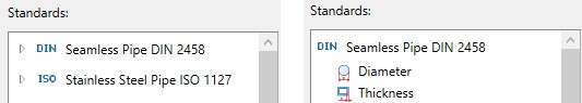
After selecting any parameter in the right part of the window you will see the list of available values. The dependent parameter also has the list of dependencies. The dependencies show, which values the control parameter can take according to the particular value of dependent parameter or in the specified interval.
The editor allows to change current standards and add the new ones. To add a standard you need to press button ![]() , select standard type (ISO, DIN and so on) from the drop-down list
, select standard type (ISO, DIN and so on) from the drop-down list ![]() and fill in all necessary fields: Name, Route Type, Profile Type, Comment, etc.
and fill in all necessary fields: Name, Route Type, Profile Type, Comment, etc.
Buttons on the toolbar will help you to cut ![]() , copy
, copy ![]() , insert
, insert ![]() , and delete
, and delete ![]() a standard.
a standard.
You can specify the following parameters for pipline standard:
Name – name of standard that will be displayed in the list.
Route Type – defines type of route that may work with this standard.
Profile Type – sets round or rectangular profile.
More information on profiles types can be found in “Parameters” section.
●Inwards, Outwards. You can select type of thickness increment Note that in this case changing method of thickness increment (Inwards/Outwards switcher in the Properties window) will be undesirable. I.e. the way of increment can be changed but it will lead to the diagnostic message.
●Use wall thickness. If the flag is set, the Thickness appears in the standards list. Without active flag you cannot specify walls thickness.
●Create one body. The flag is identical sonamed flag from the pipeline parameters. It defines the way of body creation for the current standard.
More information about the flag can be found in “Pipeline parameters” section.
After selecting parameter of standard in the left part of window, you can set its values and dependencies in the right part.
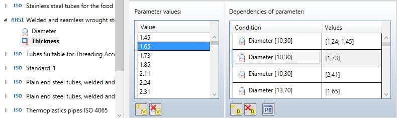
The parameter values can be set using button ![]() , dependencies are specified using button
, dependencies are specified using button ![]() .
.
To delete values and dependencies use buttons ![]() and
and ![]() or <Delete> button. To edit previously created dependency use button
or <Delete> button. To edit previously created dependency use button ![]() . After pressing the button the following dialog box will appear.
. After pressing the button the following dialog box will appear.
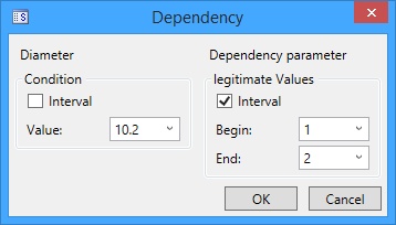
In the Dependency window you can set value or interval of the values for control and dependent parameters. To define interval you need to set flag in corresponding field.
Changes in standard
If the standard for some reason has been changed, it will not affect exisitng pipeline models based on this standard. But in this case special comment “from document” will appear near the name of the standard in the pipe parameters.
Import/Export of Standards
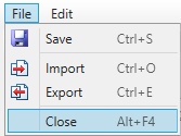
There is possibility to export and import lists of standards from XML-files using commands File >> Import, File >> Export from the menu.
There are two options available for import:
Replace. The current list will be replaced with the list from the external file.
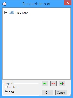
Add. You can select standards that will be added to the list. Selection list will not display standards that already exist in the list.
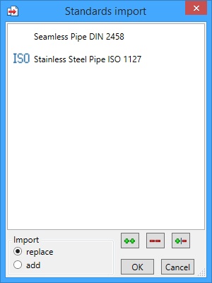
Icons at the bottom of the window allow you to perform the following actions with the list of standards:
![]() - select all standards.
- select all standards.
![]() - cancel selection of all standards.
- cancel selection of all standards.
![]() - invert standards selection.
- invert standards selection.