Boolean Operation


Boolean Operation |
|
Boolean operation creates a new body based on two or more existing bodies. As a result of the operation, a new body is created that is a combination of the source bodies.
General concepts. Operation capabilities
Types of Boolean
There are three types of Boolean operations:
● Addition. This operation results in a body which is the union of all pieces of the bodies participating in the operation.
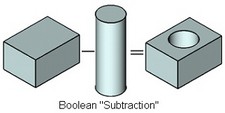
● Subtraction. This operation subtracts one body from another body.
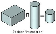
● Intersection. This operation results in the body which is the intersection of the participating bodies, being their common part.
Boolean operands
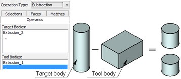
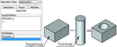
The bodies combined in a Boolean are called operands of the Boolean operation. Operands of a Boolean are the target and the tool. The bodies that are worked on are called "Target" of a Boolean. The bodies used for the manipulations are called "Tool". Different result is obtained, depending on which of the body was the target and which was the tool.
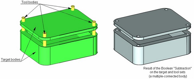
A Boolean can also be defined on a set of bodies, some of which are selected as the target and other as the tool. In such an operation, all targets are united in one body, and all tools are united in another one. Then, a Boolean is performed on these bodies. This results in a single multiple-connected body.
Results of Boolean operations
Operands can be either solids or sheet bodies. By selecting various combinations of operands and using different options, you can get a variety of results of a Boolean operation.
Note that in certain cases, inadmissible combinations of operand types in a Boolean will not produce a valid result.
Below, we review common operand combinations and results of the respective Boolean operations.
Selecting type of the resulting body
In some cases, a Boolean can produce either a solid or a sheet body. The user can select the type of the resulting body with the help of the parameter "Create body".
This complementary option allows selecting one or another type of the resulting body, if possible under the rest of conditions. If the selected body type cannot be generated by the operation, this parameter setting will be ignored.
Sheet body treatment
A sheet body used as an operand in a Boolean, can be treated in the command as the sheet body proper or as a semi-space. Different results will be obtained, depending on the treatment of the sheet body and on whether it is used as the target or the tool.
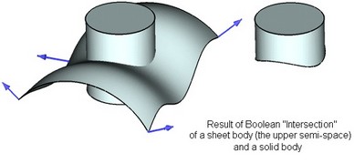
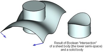
If a sheet body operand is treated as a semi-space, then the vectors normal to the sheet body surface will be displayed in the scene. Direction of those vectors specifies which semi-space is selected, determining the operation result.
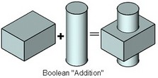
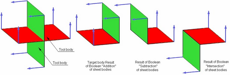
"Addition" operation
The following are the results of the Boolean "Addition" per different operand type combinations:
Target |
Tool |
Result |
solid |
solid |
solid |
sheet (semi-space) |
solid |
sheet |
solid |
sheet (semi-space) |
solid |
sheet (semi-space) |
sheet (semi-space) |
sheet (with corners) |
sheet |
sheet |
sheet (sewn) |
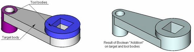
Solid + Solid
If both the target and the tool are solid, then the operation results in a single body uniting all parts of the bodies subjected to the operation.
Sheet + Solid
The operation results in a sheet, which is "stamping" of the sheet with a portion of the solid body. Depending on the selected semi-space, the "stamping" is created either on the bottom or on the top part.
Note that the sheet must fully intersect with the solid.
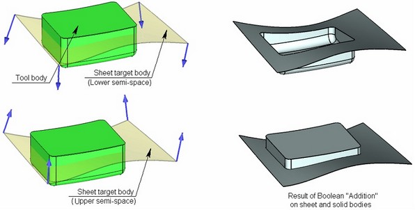
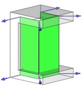
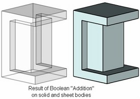
Solid + Sheet
If a solid is selected as the target, while a sheet - as the tool, then the default result of the Boolean "Addition" will be a solid. The faces of the sheet body will create an additional volume for the solid.
The sheet body must be defined as a semi-space in this instance of the command.
Note that this type of the Boolean operation requires, that the sheet body formed a closed volume when united with the solid. Otherwise, the operation cannot create a valid result.
When selecting a sheet body, pay attention to the normal vectors direction. An invalid result can be produced due to certain normal directions. In such a case, you need to specify the other semi-space by the parameter "Operands treatment".
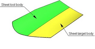
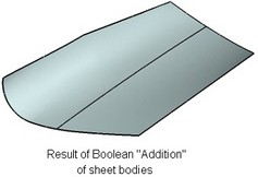
Sheet + Sheet
Adding two sheet bodies results in a sheet. For successful operation creation, the faces of the sheet bodies must either have a common edge or coincide within some region. This functionality is similar to the "Sew" operation. The difference is in that the Boolean "Addition" does not eliminate gaps between the bodies, while the "Sew" attempts to create a new continuous surface.
"Subtraction"operation
Following are the results of the Boolean "Subtraction" for different operand type combinations:
Target |
Tool |
Result |
solid |
solid |
solid |
sheet |
solid |
sheet |
solid |
sheet (semi-space) |
solid |
sheet (semi-space) |
sheet (semi-space) |
sheet (with corners) |
Solid - Solid
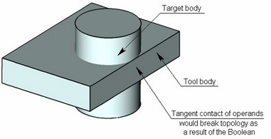
The result of the Boolean "Subtraction" of one solid from another one will be the target body with the removed tool portion of the volume.
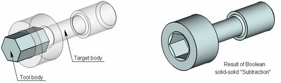
When creating the Boolean "Subtraction", the system guards from a situation in which the target body would have portions with zero-thickness walls. This would break the model topology.
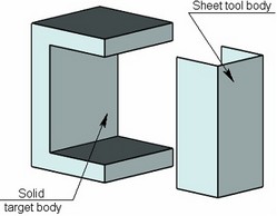
Sheet - Solid
When a solid is subtracted from a sheet, an opening is created in the sheet body, repeating the shape of the solid tool.
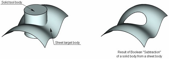
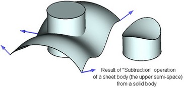
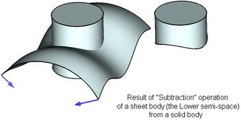
Solid - Sheet (semi-space)
Subtracting a sheet body from a solid leaves a part of the solid body cut off by the sheet. In this case, the sheet body must be defined as a semi-space. Depending on the selected semi-space, either the upper or the lower portion of the solid remains. This type of the Boolean is analogous to the "Cut" operation.
"Intersection"operation
The results of the Boolean "Intersection" operation on various combinations of the operand types are:
Target |
Tool |
Result |
solid |
solid |
solid |
sheet |
solid |
sheet |
sheet (semi-space) |
solid |
solid |
solid |
sheet (semi-space) |
solid |
sheet (semi-space) |
sheet (semi-space) |
sheet (with corners) |
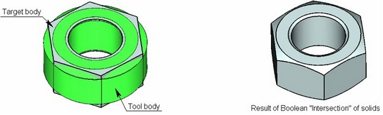
Solid Solid
The result of intersection of two bodies is the body that is the common part of all operands.
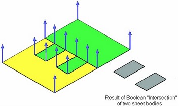
Sheet (semi-space) Sheet (semi-space)
If sheet bodies coincide within some region, then their common portion is left as a result of the Boolean "Intersection".
Sheet Solid
If a sheet is selected as the target while a solid as the tool, then the Boolean "Intersection" operation will result in creation of a sheet which is the common part of the two operands.
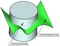
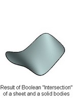
Solid Sheet (semi-space)
The result of performing the Boolean "Intersection" of a sheet body treated as a semi-space, and a solid, will be the portion of the solid body cut off by the sheet. The result of performing this operation is similar to the result of the Boolean "Subtraction" of a sheet (semi-space) from a solid. The difference is in that the result of the "Intersection" operation is the other part of the solid. Note that the order of selecting operands does not affect the result.
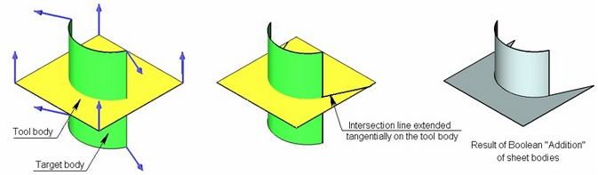
Boolean operations on sheet bodies (semi-spaces)
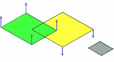
One indication to using Boolean operations on sheet bodies is creation of corners. In this case, the sheets specified in the command must intersect and be treated as semi-spaces. Depending on the normal directions of the sheet surfaces and the type of the used Boolean operation, different sheet bodies are produced as a result. Note that the normal directions are preserved on the resulting body.
If one sheet does not fully intersect the other one, the Boolean won't work. To fix the situation, an option is provided among the Boolean operation parameters for extending edges of the target or the tool up to the next edge or the body boundary. In this case, the intersection line between these two bodies will be extended tangentially up to the selected edge or to the boundary of one of the operands.
Global and local Boolean operations
If sheet or solid bodies are selected as operands, we will call such instances of the Boolean operation "Global". When creating such a Boolean operation, the system automatically determines which faces of the bodies are involved in the operation, and finds their intersections. If a Boolean involves geometrically complex bodies or the large number of operands, then the search for all intersections may noticeably delay the command execution.
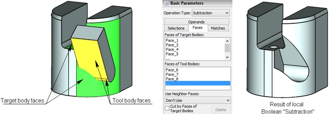
Besides the "Global" Boolean operation, T-FLEX also introduces the "Local" Boolean operation. Unlike the "Global" Boolean operation whose operands are always bodies, the "Local" Boolean operation allows selecting faces, besides the body operands. The operand faces can be selected with the help of the tab "Faces" in the operation's parameters. In some cases, use of the "Local" Boolean operation saves considerable time on the model regeneration, as compared with the "Global" Boolean operation, since the intersections will be searched only among the specified faces when processing the operation. For example, to make a hole in a rather complicated body, you can specify the faces to be intersected in the operation parameters if you know in advance that just few faces will be intersected.
You need to be careful when selecting faces for the "Local" Boolean operation. An invalid body may result from incorrect selection of faces.
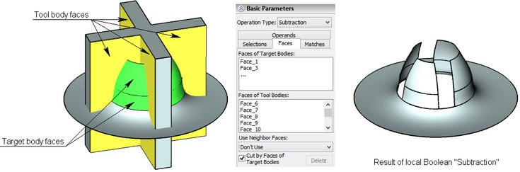
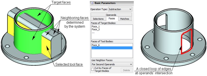
Selecting specific faces for the operands of a "Local" Boolean operation with the option "Cut by Faces of First Operands" turned on, allows creating bodies like those shown on the diagram below. In this case, the intersection lines between the operands' boundaries will be determined first, and then closed loops will be formed along these intersection lines and the boundaries of the target operands' faces, in order to create a Boolean operation.
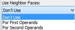
In some cases, the option "Use Neighbor Faces" can be conveniently used for the target or the tool. All you need is select one face of an operand, and the system will automatically define the neighboring faces in such a way, that the intersection lines between the operand faces form closed loops. In this case, changes in the number of faces making a closed loop due to operand modifications, will not invalidate the result of the Boolean operation.
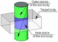
Selective Boolean operations
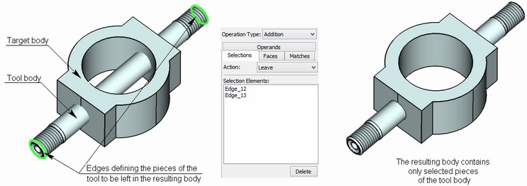
When intersected, operand faces create common edges. Those edges divide the bodies of the operands into pieces. There are inner pieces (shared by the operands) and outer pieces of operands. When creating a Boolean operation, you can specify the outer pieces of the operands that will be left in the resulting body, or, on the contrary, excluded from it. A piece of an operand is defined by topology elements, such as vertices, edges are faces. To select a piece of an operand, you need to specify one of such elements in the operation parameters on the tab "Selections". The diagram below shows an example of using a selective Boolean "Addition" operation, whose execution results in a body containing only selected pieces of the tool. |
|
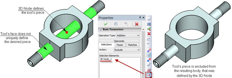
In some cases, the selected topology element does not explicitly defines the desired piece. For example, as shown on the diagram below, the selected face belongs to several outer pieces of the tool. To uniquely determined the desired piece, one needs to create a 3D node on this face, and then select this 3D node by the option "Select point that indicates part of operand". In this case, you do not have to select the face.
Setting element matches
In the cases when the operands have coinciding regions, the command provides the function of additionally specifying topological correspondence of the operands' regions. The command will select the appropriate algorithm for creating the Boolean operation based on this information.
This function allows:
1. Speed up regeneration of the Boolean operation due to the particular specified type of contact.
2. Successfully create the Boolean operation in the cases when this would be impossible without knowing the match. An example of such situation is a contact between a spline and an analytical surface (a Boolean on a cylinder and a face of a helix on the diagram below).
The command has provisions for four types of matches:
● Exact match – the boundaries of topological elements coincide within the specified tolerance.
● Contained – the boundary of the second element lies fully within the extents of the first element's boundary.
● Overlap – the boundary of one element partially coincides with the boundary of the other element.
● Imprinted – the boundaries of the imprinted topological elements coincide.
The table below presents the description of match types for operands of various topology:
Match Contact type |
Exact match |
Contained |
Overlap |
Imprinted |
Vertex Vertex |
– |
– |
– |
Projections of operands' vertices coincide |
Edge Edge |
Edge curves coincide within specified tolerance. Respective vertices of edges coincide within specified tolerance. |
Edge curves coincide within specified tolerance. Extents of the second edge are fully within the first edge |
– |
Imprinted operands' edges coincide |
Face Edge |
– |
Edge curve lies on the surface of the face within specified tolerance. Edge lies fully within the extents of a face. |
Edge curve lies on surface of the face within specified tolerance. Edge may intersect the face boundary (edges). |
– |
Face Face |
Surfaces of faces coincide within specified tolerance. Each edge of first face has matching edge on second face. Inexact coincidence of edges is allowed. |
Surfaces of faces coincide within specified tolerance. Second face is fully contained within first face. No edge of second face intersects boundaries of first face. Edges may coincide. |
Surfaces of faces coincide within specified tolerance. Boundary of one face may intersect boundary of the other face. Edges of the faces may coincide. |
– |
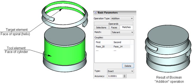
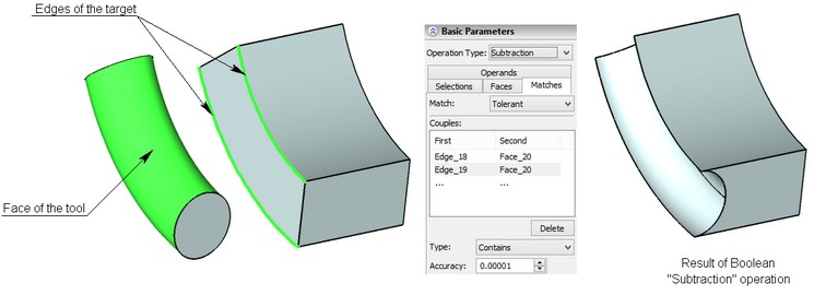
A match can be exact or approximate. An exact match implies that the operands have only the described contacts and no more overlaps or intersections. If the inexact ("tolerant") matching is set, the system will be searching for other intersections of operands, besides the specified contacts. This type of processing takes more time, compared to the exact matching; however, in some cases this is the only possible way of creating a Boolean operation.
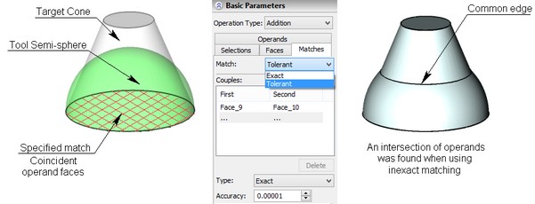
The diagram below illustrates defining a match in a Boolean "Addition" operation on a semi-sphere and a cone with the common base. If the match is defined as coincident faces at the base, and the exact option is used, then the Boolean operation will not be possible to create, since there is another common edge in the intersection of the operands, which is not described among the matches. In this case, the only option is use of the inexact matching that will find this other intersection during the processing.
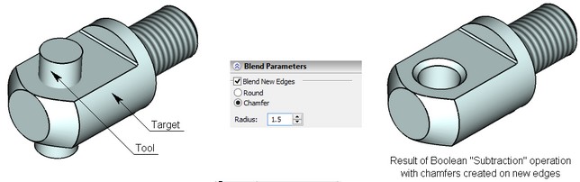
Blending new edges
Another capability of Boolean operations is blending new edges. By new edges, we mean the edges created as a result of intersecting faces of the operands. As the operands' geometry changes, the system will automatically track the increasing or decreasing number of new edges and create blending. You can select the type of blending in the command: round or chamfer, and specify the blending radius.
Missing operands
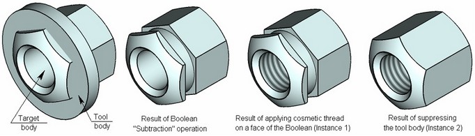
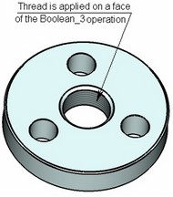
When creating a Boolean operation, you can turn on the option "Allow missing operand". This technique is often used in parametric models, when one of the model's elements needs to be excluded in some instances. As shown on the diagram below, a nut can be in two instances: with and without grooving. To realize both instances in one model, one can suppress the tool, while maintaining the rest of the consequent operations based on the Boolean (in the example, this is the cosmetic thread on the face of the Boolean operation).
If this option is turned off, then an error will be output when recreating this Boolean operation with the operand suppressed.
Creating Boolean operation
The Boolean operation creation command can be called in one of the following ways:
Icon |
Ribbon |
|---|---|
|
3D Model → Create → Boolean |
Keyboard |
Textual Menu |
<3B> |
Operation > Boolean |
The automenu and the property window are used together in the command. These work together and enhance each other. The state of the automenu depends on the step of defining the operation and on the purpose and type of the objects being selected.
The following steps are to be done to create the operation:
1. Select Boolean operands.
2. Select the type of the Boolean operation.
3. Specify operands' pieces for creating a selective Boolean operation (optional).
4. Define element matches (optional).
5. Define additional parameters (if necessary).
6. Define blending parameters (optional).
7. Confirm operation creation.
Main operation parameters
Selecting operands
Selecting operands of the global Boolean operation
To select operands of a global Boolean operation, use the following option:
![]() <1> Select Boolean operands
<1> Select Boolean operands
At this point, the options become available in the automenu:
![]() <F> Select 1st body
<F> Select 1st body
![]() <S> Select 2nd body
<S> Select 2nd body
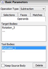
As one of these options is activated, the input focus switches to the respective pane of selecting targets or tools in the property window. Vice versa, as you switch the focus between the selected operands panes in the property window, the respective options activate in the automenu. Target and tool bodies can be selected either directly in the 3D scene or in the 3D model tree. Target bodies are highlighted green in the scene, tools – yellow. An operand selected in the property window is highlighted blue in the scene. To delete any operand from the list, select it in the "Properties" window, and then press the button [Delete]. |
|
To cancel selection of all operands, use the option:
![]() <D> Cancel selection of all operands
<D> Cancel selection of all operands
Once the Boolean operation is created, the operand bodies will be removed from the scene, with only the resulting body left. For each operand, you can turn on the option "Keep source body". In this case, the body of the operand with this option engaged will be left in the scene upon creating the operation.
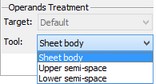
If a sheet is selected as an operand, you need to specify the treatment for this body. There are three ways of treating a sheet body: as a sheet proper, or as an upper or lower semi-space. Depending on its definition by the system, the resulting Boolean operation will be created differently. A sheet body's treatment can be defined by selecting the appropriate value in the combo box of the operands' treatment parameters. |
|
Selecting operands for the Boolean operation
To enter the mode of selecting faces for creating a local Boolean operation, one can use the automenu option:
![]() <3> Select local faces
<3> Select local faces
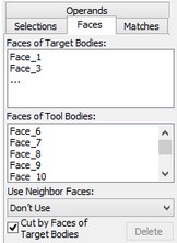
Alternatively, to activate this mode, you can switch to the "Faces" tab in the "Properties" window.
At that time, the following options become available in the automenu:
![]() <F> Select local faces for first Operands
<F> Select local faces for first Operands
![]() <S> Select local faces for second Operands
<S> Select local faces for second Operands
Once the operands are selected, you can proceed with selecting bodies' faces for creating a local Boolean operation. You can do this in the scene by the mentioned automenu options or by focusing on the pane of the "Faces" tab. When creating a Boolean operation, you can skip selecting operands and directly proceed to the mode of selecting faces. In this case, the bodies, whose faces are selected, will be automatically added as operands on the respective tab in the operation parameters. Highlighting of the target and tool faces is analogous to that of the bodies-operands. To remove a face, select it in the list on the "Faces" tab, and then press the button [Delete]. In some cases, you may need to turn on the option "Cut by Faces of Target Bodies" to insure the correct operation result. To cancel selection of all local faces, use the option:
|
|
When creating a local Boolean operation, you can engage faces adjacent to the selected face. To do this, select the respective entry in the combo box of the "Use Neighbor Faces" parameter. |
|
Selecting Boolean type
Selection of the operation type is done either via the parameter "Operation Type" in the property window, or by the following options in the automenu:
|
|
When the Boolean operation is called first time in a session, the Boolean operation type "Addition" is automatically set in the automenu. On subsequent calls to the Boolean, the default button will be the type used in the previously called Boolean.
Selecting operands' pieces
To create a selective Boolean operation, use the following option:
![]() <2> Select parts of operands
<2> Select parts of operands
Alternatively, to activate this mode, you can switch to the "Selections" tab in the "Properties" window. In this case, the following options become available in the automenu:
![]() <F> Select element that indicates part of operand
<F> Select element that indicates part of operand
![]() <H> Select point that indicates part of operand
<H> Select point that indicates part of operand
![]() <D> Cancel selection of elements that indicate parts of operands
<D> Cancel selection of elements that indicate parts of operands
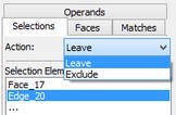
With these options, you can select the elements defining the operands' pieces. The names of the selected elements will be added to the list on the "Selections" tab in the "Properties" window. On the same tab, you can select the action for the selected pieces of the operands: leave those in the resulting body, or exclude. The selected action will work on all selected pieces of the operands. |
|
Setting element matches
To define element matches, use the option:
![]() <4> Select matches
<4> Select matches
Alternatively, to activate this mode, you can switch to the "Matches" tab in the "Properties" window. Then, the following options become available in the automenu:
![]() <F> Select first match Element
<F> Select first match Element
![]() <S> Select second match Element
<S> Select second match Element
![]() <D> Cancel match selection
<D> Cancel match selection
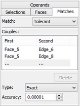
Use these options to select pairs of elements for defining matches. The names of the selected elements are displayed on the "Matches" tab in the "Properties" window. Each pair of elements can be assigned the exact or approximate ("tolerant") matching option. The type of match is selected from the "Type" combo box on this tab. Note that the set of match types in this combo box can vary, depending on the particular combination of element topologies in a pair (see the table in the topic "Setting element matches"). The matching tolerance can be specified on this tab. |
|
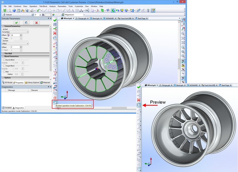
Preview of Boolean Operations Results
To preview the result of a Boolean operation and also the changes introduced by a Boolean operation it is required to use the preview option in the automenu or a similar button in the properties window:
|
<F5> |
Preview result of operation |
|
<Ctrl+F5> |
Preview changes introduced by operation |
Additional operation parameters
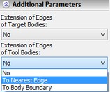
Extending operands' edges
If sheet bodies defined as semi-spaces are used as operands in the command, then edges may need to be extended to achieve intersection of the operands in order for the command to succeed with the Boolean operation creation. To do this, select the type of the object, up to which the edges of the target or tool body are to be extended. This can be done using the respective additional parameters. |
|
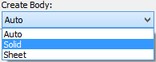
Selecting the type of resulting body
If a Boolean operation permits either the solid or the sheet result, then the desired type can be set by the option "Create body" in the additional operations parameters. By default, the command will create the resulting body of the preferred type. |
|
As was mentioned earlier, this option is complementary. If the selected type of the resulting body is impossible, this parameter setting will be ignored.
Use Pattern Copying
If a 3D array is used as one of the operands, you can significantly reduce the time of executing the Boolean operation by turning on the parameter "Use Pattern Copying".
![]()
Provision for a missing operand
By turning on the "Allow missing operand" parameter in the Boolean being created, you will be able to suppress one of the operands in the future, and still keep the result of the Boolean operation.
![]()
Blending new edges
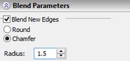
To turn on the mode of blending newly created edges resulting from the intersection of the target and tool bodies, turn on the parameter "Blend New Edges". After that, a group of parameters becomes accessible for selecting the blend type ("Round", "Chamfer") and amount of blending (the parameter "Radius").
Material of newly created faces
To determine the material to which the result of the Boolean operation is applied, the combination of parameters is used. In addition to material parameters found on the “General” tab and common for all operations (the “Source”, “Main”, “Covering” parameters), the material assignment parameter for the new faces, which are created as a result of applying Boolean operation, is also taken into account. This parameter is located on the “Parameters” tab and is called “Material of new faces”.
This parameter can take one of the three values:
●“Material of first operand”. In this case the main material or the material of the covering (if it is specified) will be assigned for the new faces according to the parameters of the first operand. If there are several first operands and they are with different materials, then on the new faces the material of that operand which participated in formation of these faces will be saved;
●“Material of second operand”. For this value of the parameter, on the new faces of the resulting body the material will be transferred from those faces of the second operand which participated in their formation. This can be either the main material or the material of the covering (if it is specified), and even the material of the “Material overlap” operation. For example, as a result of execution of the Boolean operation “Subtract” between the first operand with the material steel and the second operand with the material black plastic, the material black plastic will be put on the created faces of the resulting body. If there are several second operands and they are with different materials, on the new faces the material of that operand which participated in formation of these faces will be saved.
●“Main material of first operand”. The action of this parameter is analogous to the first parameter (“Material of first operand”), except the case when the material of the covering is specified. In this case the material of the covering is not used on the new faces. For example, if in a part with the main material “Steel” and with covering “Copper” we create a hole with the help of the Boolean operation, the hole inside will appear as steel in accordance with the main material. |
|
Specifics of handling Boolean operations
Boolean operation representation in "3D Model" window
Upon creation, a Boolean operation is put in the "Boolean" folder in the "3D model" window. An icon is displayed before each Boolean operation, denoting the operation type (![]() Addition,
Addition, ![]() Subtraction,
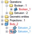
Subtraction, ![]() Intersection). Booleans appear in a special way in the 3D model tree. When expanding the Body's structure, the Boolean appears as an icon before the tool body. The diagram on the right hand side shows "Boolean_2": an intersection of the target "Extrusion _0" and the tool "Extrusion_1".
Intersection). Booleans appear in a special way in the 3D model tree. When expanding the Body's structure, the Boolean appears as an icon before the tool body. The diagram on the right hand side shows "Boolean_2": an intersection of the target "Extrusion _0" and the tool "Extrusion_1".
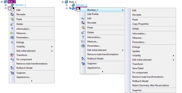
Upon right clicking ![]() the icon before a tool operand in the model tree, the Boolean operation context menu appears. Alternatively, the Boolean context menu can be accessed as the context menu of the tool body in the model tree.
the icon before a tool operand in the model tree, the Boolean operation context menu appears. Alternatively, the Boolean context menu can be accessed as the context menu of the tool body in the model tree.
Creating Boolean operation in the 3D model tree
You can create a Boolean in the 3D model tree without explicitly calling the creation command.
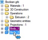
Select a body in the 3D model tree, and then Drag&Drop it to another body by dragging the mouse with the left button depressed. This would automatically create the Boolean "Addition". By additionally holding down the <Ctrl> key, the Boolean "Subtraction" will be created. If, instead of <Ctrl>, you hold the <Shift> key, the Boolean "Intersection" will be created. The dragged body is the tool, and the body, to which the other is dragged, is the target.
Automatic Boolean creation combined with creating other operations
Numerous operations of T-FLEX CAD allow automatic creation of a Boolean. The body being created in those operations is always the tool of the Boolean. The target is selected among all existing bodies of the 3D model.
It should be noted that when creating these operations the preview displays the result of the automatic Boolean only upon creation of the operation. When editing the operation the preview is not displayed. If the Boolean operation created automatically does not have a result, then only the operation being created will be seen on the preview.
To create a Boolean operation, do the following:
1. Turn on the Boolean creation mode by the automenu option
![]() <Ctrl+B> Select original body for Boolean operation
<Ctrl+B> Select original body for Boolean operation
A Boolean is created when the icon is pushed.
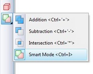
2. Select the type of the operation from the pull-down list under the above option:
![]() <Ctrl+'+'> Addition
<Ctrl+'+'> Addition
![]() <Ctrl+'-'> Subtraction
<Ctrl+'-'> Subtraction
![]() <Ctrl+'*'> Intersection
<Ctrl+'*'> Intersection
![]() <Ctrl+l> Smart mode
<Ctrl+l> Smart mode
Operating principles of the Smart mode:
●If the body being created and the existed selected body have intersection of volumes - the type of Boolean operations: subtraction.
●If the body being created lies entirely within the selected body - the type of Boolean operations: subtraction.
●If the body being created touches and selected body touch each other - the type of Boolean operations: addition.
●If conditions set out above are not met, or a selected body lies inside the created, or error occurred determining the type of penetration, then, Boolean type is not defined - the Boolean operation will not be created.
3. Select the target body for the Boolean (optional in some cases), using the automenu option
![]() <Ctrl+T> Select Target Body for Boolean
<Ctrl+T> Select Target Body for Boolean
If only one body exists in the scene, it is selected automatically. The new body created by the extrusion operation becomes the tool body of the Boolean.
Upon confirming operation creation, first the body is created by the extrusion operation, and then the specified type Boolean is performed.
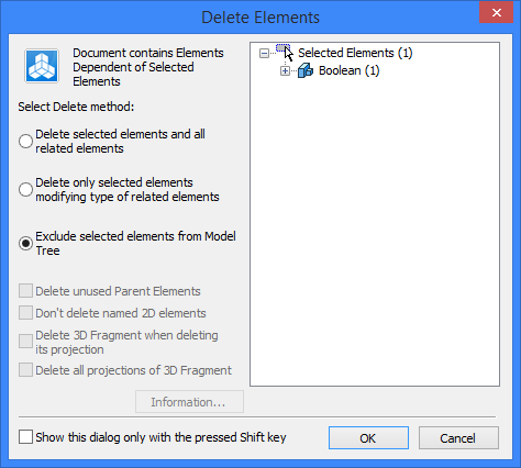
Deleting Boolean operation
If a Boolean is at the top level of the tree, then, upon its deletion, the operand bodies of this Boolean operation will be left in the model. However, if a Boolean operation already has dependents, then the "Delete Element" dialog box will be launched upon its deletion. If you select the option "Exclude selected elements from Model Tree" in this dialog box, then another dialog will be launched, "Select operation to reassing child operation", that offers selecting one of the Boolean's operands on which all dependents of the Boolean would be transferred.
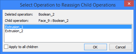
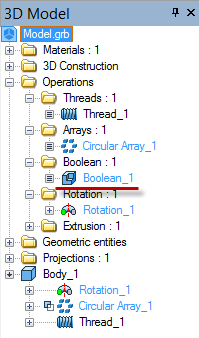
The diagram below shows the structure of the Body_1. First, a Boolean “Subtraction” of “Circular Array_1” from the “Rotation_1” operation was done, and then the “Thread_1” was applied on the Boolean's face. Suppose, you attempt to delete the “Boolean_1” with the option of excluding the element from the model tree. Now, if you select the “Rotation_1” operation in the “Select operation to which all references will be re-assigned” dialog box, then the operation “Thread_1” will become a child of the “Rotation_1” operation.
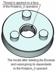
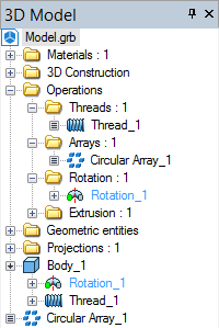
When one of the operands is deleted and the element excluded from the model tree, the Boolean itself will also be deleted.
Boolean operations on 3D fragments
Use of 3D fragments as operands is a unique feature of T-FLEX CAD. This significantly expands capabilities of creating parametric 3D models and assemblies. At the time of inserting a 3D fragment into an assembly, there is a provision of creating a Boolean with the assembly's bodies. For details on capabilities of using a 3D fragment as an operand, refer to the chapter "3D Assemblies" and its section "Creating Boolean operation based on 3D fragment", and the chapter "ST: Set Document Parameters", the section "The tab '3D'".
When you insert a 3D fragment with option for automatic Boolean operation creation, the preview displays not only the inserted fragment, but also the result of the Boolean operation.
Applying thread by Boolean operation
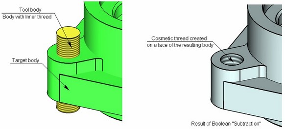
If a cosmetic thread is applied on a face of one of the operands, and this face is in contact with the faces of the other operand, then it is possible to automatically create a cosmetic thread on the face of the resulting body. For example, as shown on the diagram below, a body with a cosmetic thread on its face is subtracted from a base body. In this case, a cosmetic thread is automatically created on the newly created face of the resulting body.
Note that the thread on the face of the tool operand must be "Inner" in order for the thread in the hole of the resulting body to be created "Inner" as well.