Three-Face Blend


Three-Face Blend |
|
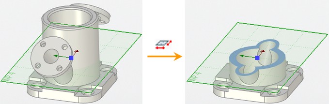
The three-face blending operation creates a blend surface from one set of smoothly connected faces to another such set. The blend surface will be constructed tangent to yet another, third set. A typical situation addressed by this operation is creation of a smooth transitional surface between two opposite faces and along the narrow strip of the side surface of thin-wall parts. The sets of faces for blending are not required to share common edges (intersect).
Blending can be performed over solid bodies as well as sheet bodies. This operation can be considered as a special case of the face-face blend, separated into a dedicated command. Since the three-face blend shares many concepts with the face-face blend, first refer to the "Blending faces" section for details on certain terms and concepts.
Main concepts. Operation capabilities
General operation concepts
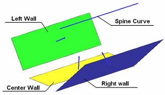
Three sets of faces make the basis of the “Three-face blend” operation. These are called “right”, “left” and “center” walls. The sets of faces of the left and right walls should have between themselves smooth mates, a set of faces of the middle wall can be mated at a small angle (not more than 5 °). The walls themselves are not required to connect smoothly with each other. All sets of faces can belong either to the same solid body or to one, two or three sheet bodies. Three-face blends can’t be created between walls belonging to different solid bodies or mixed sheet and solid bodies.
Blending Form
There are two types of blending of three faces: spherical and disk.
For a spherical type, the blending surface is formed by moving an imaginary sphere inscribed between the walls along the entire length of the walls, forming a smooth tangential conjunction at the points of contact with them. The cross-sectional shape of the blending surface is calculated as a spline.
For disc type, the blending surface is formed on the basis of a set of cross-sectional planes and a guide. Planes are built perpendicular to the guide and contain three points of contact where the blending surface touches the walls. The cross-sectional shape of the blending surface in the plane is always calculated as a circular arc that fits in such a way as to ensure a tangency to each wall.
Original configuration Resulting blend
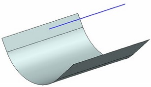
The guide spine is always represented by a 3D path. The spine may not have sharp corners. If the spine is too short for defining all cross sections, it is extended by straight segments tangent at the ends. If the length of the guide is redundant, then the system tries to choose the part of the 3D path it needs.
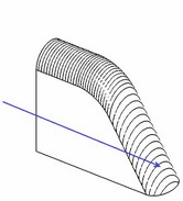
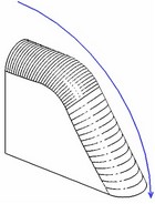
The figures show blend surface geometry dependency on the guide spine
If the left and center walls are adjoining then their common edge (the set of edges) may be used as the guide spine. In this case, selection of the guide spine is optional.
In the case of the use of disk-type construction of the blending surface, when the edge between the left and middle walls has a complex shape, to ensure a successful result between the faces, it is necessary to create a new guide of a simpler shape in comparison with the edge, which approximately repeats its shape. Let's consider two typical examples.
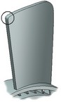
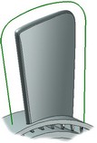
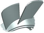
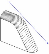
Example 1. It is required to create a blending of the side part of the fan blade with the use of disk construction type. In this case, the system may not use the edge between the left and center walls due to the following reason. The edge has a too small radius in the circled area. The blend cross sections would intersect each other if constructed normal to the edge. An additional spine (a 3D path) helps creating a blend in this case that approximately repeats the shape of the edge yet avoids the mentioned traps. |
|
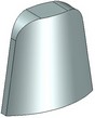
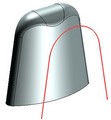
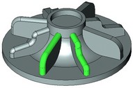
Example 2. In this example, the left and right walls are cone fragments. The part gets wider in the middle. At the first glance, the edge radius is not too small. However, due to the widening part and edge curving in the opposite direction, the system considerably increases the radius of the blend surface that again results in self-intersections. Using a flat spine of the shown shape helps easily create the blend surface. |
|
Adjacent Smoothing
The mode of selecting consecutively paired faces allows the system to automatically select a connected sequence of smoothly adjoined faces of the required wall when specifying one of the faces included in this sequence.
|
|
If the adjacent faces of the middle wall are conjugated at an angle, the system allows you to set the angle at which these faces will participate in blending.
|
|
Result
When blending three faces of a solid body, the result will always be in the form of a solid body.
When blending three edges of the sheet body, or three sheet bodies, the system allows to determine the type of the resulting blending:
●No Trim. The blending surface does not join the walls; walls are removed. The result is a sheet body.
●Trim Both. The left and right walls are cut off at the points of contact with the blending; the blending surface does not join the walls. The result is individual sheet bodies.
●Trim and Sew. The left and right walls are cut off at the points of contact with the blending surface; blending surface joins the walls. The result is one sheet body.
●Create Solid. The left and right walls are cut off at the points of contact with the blending surface; blending surface joins the walls and forms a closed space. The result is a solid body.
●Auto. The system independently selects the optimal blending result.
|
|
|
|
|
The Initial Set of sSheet Bodies |
No Trim |
Trim Both |
Trim and Sew |
Create Solid |
The system also provides the ability to create a blending in the form of a separate body, while maintaining the topology of the original bodies.
|
|
|
|
The Initial Set of sSheet Bodies |
Result |
Original solid body |
Result |
Sometimes situations arise when several blending surfaces may exist for a selected set of walls. You can leave them all or specify one specific solution. The system selects the solution closest to the selected 3D point. The 3D point can be a 3D node, a vertex or a middle of an edge.
|
|
|
Source body |
All solutions |
3D node solution |
Trimm Blending Surface
Using flat edges or work planes, you can set a restriction of the blending zone. One bounding plane divides the blending surface into two parts, leaving one of them in the scene. In total, no more than two bounding planes can be specified. Two planes can limit the central part of the blending surface from two sides.

The orientation of the blending boundary depends on the bounding plane and the chosen method of the blending shape. When the Trimming parameter is set, the blending boundary passes along the boundaries of the bounding plane. Otherwise, the blending boundary passes perpendicular to the direction of the blending surface through a point formed in one of the following ways: |
|
●The intersection of the bounding plane and the top blending (for spherical shape blending); |
|
●The intersection of the bounding plane and the given guide (for the disk shape blending). |
|
Trimming by walls (Ends processing)
When creating blending faces, you can choose how to trim the edges of the blending surface. The geometry of the walls themselves when cutting the blending surface is not broken. Total
There are four ways to trim:
●No Trim. In this case, the blending surface is extended beyond the boundaries of all walls.
●By Both Walls. The blending surface is cut along the borders of the left and right walls. In this case, the side edge of the blending surface is formed in such a way as to ensure contact with the side edges of the trimming walls.
●By Short. The blending surface is trimmed along the least distant wall edges.
●By Long. The blending surface is cut along the most distant edges of the walls.
|
|
|
|
|
The Initial Set of sSheet Bodies |
No Trim |
By Both Walls |
By Short |
By Long |
Additionally, the system makes it possible not to take into account the middle wall when creating a blending surface. For example, the option may be useful when creating a body with trimming along the wall in the By Short mode or By Long.
|
|
|
The Initial Set of sSheet Bodies |
By short, taking into account the middle wall |
By short, without taking into account the middle wall |
|
|
|
The Initial Set of sSheet Bodies |
By long, taking into account the middle wall |
By long, without taking into account the middle wall |
The methods of trimming No Trim, By Short, By Long can be used only if the end result is obtained in the form of a sheet body.
Operation defining steps
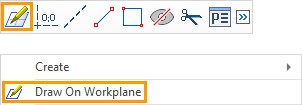
The operation creating command can be called via one of the following ways:
Icon |
Ribbon |
|---|---|
|
3D Model→ Create → Blend → Three Face |
Keyboard |
Textual Menu |
<3DT> |
Operation > Blend > Three Face |
The property window and the automenu are used for handling the command and defining necessary components. These work simultaneously and enhance each other. The object selection modes can be manipulated via either the automenu or the property window.
To create the operation, follow the following steps:
●Select first set of faces (the left wall)
●Select second set of faces (the center wall)
●Select third set of faces (the right wall)
●Set blending type (if necessary)
●Select a guide (if necessary, depending on the type of blending)
●Set result parameters (if necessary)
●Select trim elements (if necessary)
●Set the trim parameters by the walls (if necessary)
●Confirm operation creation
Selecting a set of faces
Normally, the operation definition begins with selecting the sets of faces between which the blend will be constructed. The left and right-wall sets are formed when one of the following automenu options is active:
![]() <L> Select left-wall face
<L> Select left-wall face
![]() <C> Select center face
<C> Select center face
![]() <R> Select right-wall face
<R> Select right-wall face
Switching between the options is done by pressing an icon button in the automenu.
Turning on an option automatically activates the respective tab on the property window. The list of selected faces of the right or left wall is displayed in the provided pane under the tab tag. Switching between the tabs of the property window also activates the appropriate options for face selection. Face selection is done using the mouse in the 3D view window. The current face highlighting color is indicated by the colored box on the tab tag for each set. |
|
To automatically select a linked sequence of smoothly conjugate faces, you need to enable the option:
|
<S> |
Smooth face chain selection mode |
After enabling this option, it is enough to specify any face of the required wall that is included into the required sequence. The remaining faces will be added automatically.
You can deselect all items at once using the option:
|
<K> |
Cancel selection |
A decorator is drawn in the middle of each face, shaped as an arrow, marking the side of the face adjacent to the blend surface. The blend is created on the side pointed at by all three arrows.
|
|
|
|
Control over the arrow directions is done via the provided "Orientation" item right of the face list pane on each tab in the property window. Selection is made in the pull-down list. For solid bodies, the direction of an arrow is determined automatically. In this case, the "Auto" option is set for all faces. For sheet bodies, the direction of faces has to be controlled manually by the user.

To change the system default arrow direction, select one of the other two available orientation settings, "Normal" or "Reverse".
To exclude a face from the wall set, simply select it in the list in the property window on the respective tab and press [Delete] button.
To ensure the participation of adjacent edges of the middle wall conjugated at an angle in the blending creation, it is necessary to set the flag in the Propagate field in the corresponding tab of the properties window and set the maximum conjugation angle of these faces. |
|
Choice of Blending Form
The selection of the type of blending is carried out using the corresponding icons in the properties window. By default, the system sets the spherical type of blending. |
|
Spine Selection
To turn on the spine selection mode, activate the following automenu option.
|
<W> |
Select guide spine |
Selection of a 3D path is done in the 3D window or in the model tree by the mouse. The name of the selected 3D path is displayed in the Guide Spine box of the property window.
![]()
Setting Result Parameters
Multiple Solution
The selection of an auxiliary point to refine the result in the case of the formation of several blending surfaces is performed after the Multiple Solution flag is checked in the properties window. |
|
To do this, activate the corresponding field and select the desired 3D point in the 3D window. The selection of the auxiliary point is canceled using the button ![]() .
.
Select Type of Walls Trimming
The selection of the type of wall trimming is carried out using the corresponding buttons in the properties window. By default, the system sets the type to Auto. |
|
To create a blending surface in the form of a separate body, you should select the corresponding flag in the properties window.
Selection of Trim Elements
To select the elements that limit the blending zone, it is necessary to use the Trimming tab in the properties window. Then determine the mode of selecting items: topological (planes, surfaces, straight lines) or geometric (faces, cycles, edges). Elements are selected using the mouse in the 3D window after activating the Element field. The direction of the resulting blending surface is determined by the value of the Orientation drop-down list. To delete a bounding element, simply select it in the list of the properties window and click the [Delete] button. The Trimming flag allows you to determine the position of the blending boundary relative to the guide. |
|
Trimming by Walls
The way to trim the edges of the blending surface is selected from the drop-down list of the Trimming by Walls option in the properties window. By default, the system sets the By Both Walls trimming method. In order for the middle wall not to be taken into account when creating the blending surface, it is necessary to check the flag in the Ignore Middle Wall field. |
|