Cut by Section


Cut by Section |
|
The cut by section operation allows creating a 3D body by cutting some portions off the original body, or getting two new bodies by cutting the original body into two parts. Operation can be applied either to solid or to sheet bodies, resulting in a body(s) of the same type.
Defining cut by section operation
The cut by section operation is called by the command "3CU: Cut By Section":
Icon |
Ribbon |
|---|---|
|
3D Model → Modify → Cut by section |
Keyboard |
Textual Menu |
<3CU> |
Operation > Cut by Section |
Upon calling the command, the automenu provides both the general system options and the specific ones for creating a cut by section and a separation:
![]() <B> Select 3D operation
<B> Select 3D operation
![]() <S> Select section
<S> Select section
![]() <W> Select intersecting Workplane
<W> Select intersecting Workplane
![]() <P> Select intersecting Profile
<P> Select intersecting Profile
![]() <K> Cancel selection of cutting surfaces
<K> Cancel selection of cutting surfaces
![]() <Tab> Switch view direction
<Tab> Switch view direction
![]() <M> Separate into two Solids
<M> Separate into two Solids
Creating a cut by section
The cut by section operation definition includes the following steps:
1. Selection of a body (the option ![]() is activated automatically). Select a body to subject to the cut by section operation in the 3D view window or in the 3D model tree. The selected body will be highlighted.
is activated automatically). Select a body to subject to the cut by section operation in the 3D view window or in the 3D model tree. The selected body will be highlighted.
2. Selection of the cutting element or set of such elements.
You can use the following cutting elements: a 3D section, a worksurface, a workplane, a 3D profile, a face of a body or a sheet body. The body is slashed along the surface of the cutting element.
You can specify a set of cutting elements. The set can include faces, 3D profiles, sheet bodies (selection of several 3D sections or workplanes is not allowed). In this case, the elements are sewed first into one sheet body, and then the cut by section is performed over the original body by the resulting sewed body. When using a set of cutting elements, the necessary conditions on these elements are: first, it should be possible to sew the elements; second, the resulting sewed body should fully intersect the original body.
Selection of the cutting elements is done using the automenu options. The 3D section and the workplane are selected using the options ![]() and
and ![]() , respectively. The set of cutting elements (faces, 3D profiles, sheet bodies) is defined by the option
, respectively. The set of cutting elements (faces, 3D profiles, sheet bodies) is defined by the option ![]() . A stand-alone 3D profile (face, sheet body) is specified as a set consisting of one element.
. A stand-alone 3D profile (face, sheet body) is specified as a set consisting of one element.
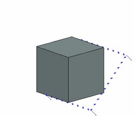
Upon selecting the cutting element, arrows are displayed on its sides pointing towards the portion of the body that will be left in the scene upon performing the cut by section. The direction of the arrows can be flipped by the option <Tab> (the icon ![]() ).
).
3. Definition of the general operation parameters (optional) by the option ![]() . The detailed description of the general operation parameters is provided in the chapter "General parameters of 3D elements".
. The detailed description of the general operation parameters is provided in the chapter "General parameters of 3D elements".
4. Confirmation for the operation creation (![]() in the automenu or in the property window).
in the automenu or in the property window).
Upon confirming the operation creation, the new 3D body will be displayed in the 3D view window.
Making body separation
To divide a body into two parts, additionally set the option:
![]() <M> Separate into two Solids
<M> Separate into two Solids
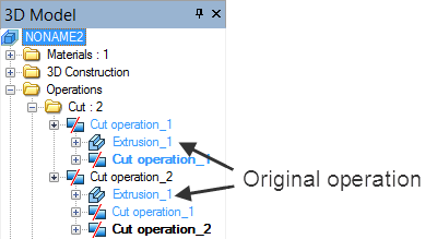
In this case, two cut by section operations with identical parameters are created automatically on the original body. Editing of such operations is also done jointly. To define parameters of one of the operations separately, call its parameters dialog box without entering the editing mode (for example, by using the context menu for this operation). The two operations are deleted separately.
Examples of creating the operation
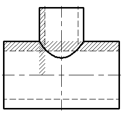
Cutting body by 3D section
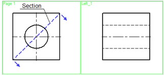
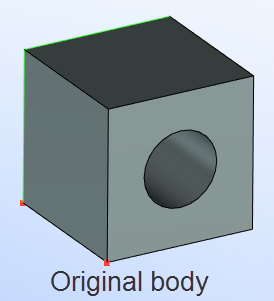
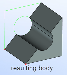
This drawing is provided with the library "Examples", the folder "\3D Modeling\Cut operation\ Cut by section.GRB".
Cutting body by face
Defining the body cutting operation by a cutting face provides interesting opportunities. Let's review the following example:
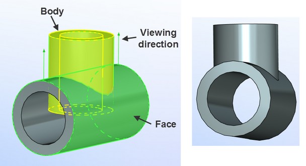
This drawing is provided with the library "Examples", the folder "\3D Modeling\Cut operation\ Cut by surface.GRB".
The drawing shown on the diagram represents an intersection of two pipes. The 3D bodies were created by two Rotation operations. Next, the required cut was made along a face belonging to one of the bodies.
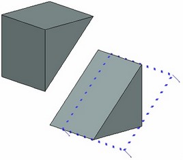
Cutting body by set of cutting elements
The drawing shows an example of cutting the body of a plate by two front faces of a pyramid.
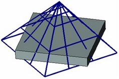
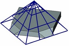
This drawing is provided with the library "Examples", the folder "\3D Modeling\Cut operation\ Cut by set of faces.GRB".
Separation of body in two parts
The diagram below shows the original body along with two resulting bodies after the Separation operation (for clarity, the resulting bodies were moved apart in the space using the command "Tools|Transformation").
This 3D model is located in the folder "\3D Modeling\Cut operation\ Cut with separation into two solids.GRB".