Spring


Spring |
|
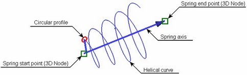
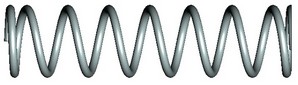
The operation Spring creates a 3D body as a conic or cylindrical helix-shape spring with round profile. The body is created by sweeping a circular profile along a helical curve defining the spring trajectory.
For speeding up modeling, a capability is provided for creating a Boolean operation together with spring creation. (This capability was described in details in the chapter "Extrusion".)
Main concepts and operation capabilities
Spring axis
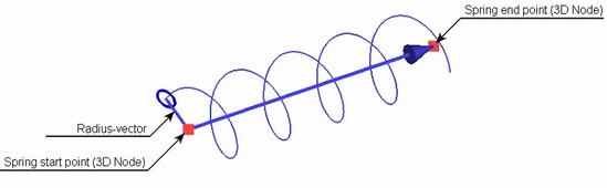
The helical curve used for sweeping the circle profile is centered about the spring axis. The axis is defined by two 3D points: the start point and the end point. 3D points can be defined by 3D nodes, as well as by any 3D object suitable for defining a point in the space. The vector defining the spring axis will be directed from the first point to the second one (those also defines the start and the end of the spring, respectively). The shape of the curve is defined by the spring parameters. The swept profile will be normal to the original curve.
Spring main parameters
The shape of the body resulting from this operation is defined by the following parameters:
● The radius of the spring strip – defines the radius of the circular profile, whose sweeping forms the body;
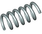
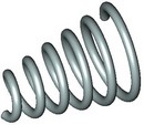
● Mean spring radii at the ends – the radii of the helical curve at the start and end of the spring (mean start and end radii are equal in the case of a cylindrical spring);
● The step (pitch), the number of coils and the free length of the spring;
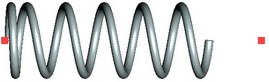
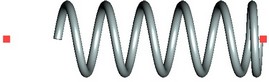
● Spring coiling direction: Clockwise (right) or counterclockwise (left).
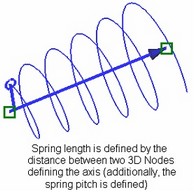
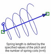
The free length of the spring can be defined as the distance between the 3D points defining its axis. In this way, it is sufficient to define just the pitch or just the number of coils – the other parameter will be calculated by the system automatically. In the cases when both the pitch and the number of the spring coils are defined, the spring length will be defined solely by those parameters.
Initial position of spring profile
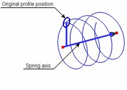
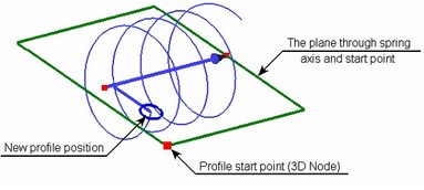
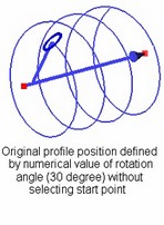
Initial position of the spring profile is set arbitrarily by the system. It can be modified by defining the desired position with the help of an additional 3D point – the start point of the profile – or by specifying the numerical value of the profile rotation angle (with respect to the original position).
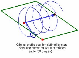
Once the start point of the profile is specified, it will snap to the plane passing through the selected point and the spring axis, along the specified start radius vector.
When both the angle of the start point and the numerical value of the rotation angle are specified, the latter is evaluated with respect to the profile position defined by the start point.
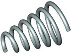
Compression and grinding of spring ends
If necessary, the end coils of the spring can be compressed (closed) and ground. The diagram below shows a spring with one coil compressed at the start, and one coil compressed and 3/4-circle ground at the end.
Spring position with respect to start and end points
If the spring length is defined by the pitch and the number of coils, you can force the spring alignment by the start or the end point.
Aligning by start point Aligning by end point
Spring operation creation
To create the operation Spring, use the command "3SP: Create Spring".
Icon |
Ribbon |
|---|---|
|
3D Model → Modify → Spring |
Keyboard |
Textual Menu |
<3SP> |
Operation > Spring |
To create a spring, do the following steps:
1. Define spring axis.
2. Define spring parameters (the radius of the wire strip, the spring main radius, etc.).
3. Select the start point for the spring profile position (optional).
4. Confirm operation creation.
Spring axis definition
The start point of the spring axis is defined by the following automenu option:
![]() <F> Select starting 3D Node of Axis
<F> Select starting 3D Node of Axis
The end point of the axis is selected option:
![]() <S> Select ending 3D Node of Axis
<S> Select ending 3D Node of Axis
The options activate one after another. Selected 3D objects are highlighted. Once the second point is selected, a vector will be displayed in the 3D scene, defining the axis of the spring, the helical guide and the profile circle. (Initially, those are assigned the default parameter settings.) Additionally, a radius-vector will be displayed, representing the mean radius at the spring start.
At this stage, you can already complete the spring operation by pressing ![]() in the property window or in the automenu.
in the property window or in the automenu.
The spring parameters can be defined in the command property window or in the operation parameters dialog box, accessible by the option ![]() .
.
Spring operation parameters definition
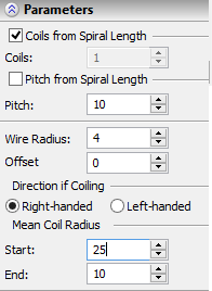
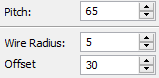
You can define main parameters of the spring in the top section of the property window – "(non-optional) Parameters". Those are wire (strip) radius, the mean radii of the spring and the direction of coiling. To have the spring length calculated by the distance between the axis-defining 3D points, set one of the flags: "Coils from Spiral Length" or "Pitch From Spiral Length". In this case, the system will automatically calculate the value of the parameter with the respective flag set (either the number of coils or the pitch). At the same time, you have to specify a numeric value of the other parameter (either "Coils" or "Pitch"). If none of the flags is set, you will have to specify both the number of coils in the spring and the pitch. The radius of the spring strip (wire) is specified in the box "Wire Radius". The winding direction of the spring is controlled by the radio group "Direction of Coiling". The start and end mean radii of the spring are defined by the parameters "Mean Coil Diameter/Start" and "Mean Coil Diameter/End". To create a cylindrical spring, specify equal values for both radii. |
|
Selection of the start point for spring profile position
The start point of the spring profile can be specified by the following automenu option (the option activates upon selecting the second axis point):
![]() <B> Select 3D Node as profile starting location
<B> Select 3D Node as profile starting location
To undo a 3D point selection, simply select another one with the same option, or cancel the selection by the option:
![]() <К> Delete starting 3D Node
<К> Delete starting 3D Node
The profile will then revert to its original position. You can enter a numerical value of the profile rotation angle with respect to the original position in the operation property window, by the parameter "Offset Angle" ("(non-optional) Parameters" section).
Defining compression and grinding of spring ends
Parameters for compression and grinding of end coils of the spring are defined in the other section of the property window – in "Optional Parameters". To compress coils at the spring start, set the flag "Start/Compress" and enter in the adjacent box the desired number of coils (for example, "0,75" or "1"). Setting the flag "Start/Ground" allows defining the portion of the first coil to grind. The compression and grinding parameters at the end of the spring are defined in a similar way – by using the flags "End/Compress" and "End/Ground".
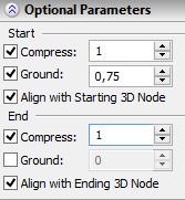
Spring alignment by start or end point
To align the spring by the start or end point, set the following flag in the property window: "Align with Starting 3D Node" or "Align with Ending 3D Node". In the case of ambiguity (when both flags are set), the system aligns the spring by the start point.