Shell


Shell |
|
Main Concepts
The operation “Shell” allows creating offset bodies and shells based on solid bodies. A shell is a hollow, thin-wall body with walls of the specified thickness. When creating a shell, some of the source solid body’s faces can be removed.
The operation “Shell” is based on the following principle: an offset surface is created for each face of the source sheet or solid body, at the specified offset distance. Depending on the user preference, the offset can be outwards or inwards of the surface of the processed body (directional or counter-directional to the normal). The offset surfaces can be used as a self-contained result – for creating offset bodies. Alternatively, offsets can be used for making a shell by confining a portion of the inner volume of the source solid body.
Shell Creation
The command 3SH: Create Shell is called by one of the following means:
Icon |
Ribbon |
|---|---|
|
3D Model → Modify → Shell |
Keyboard |
Textual Menu |
<3SH> |
Operation > Shell |
To create a shell, do the following set of steps:
●Select a face to remove or a whole solid body;
●Select a face whose wall thickness is to be defined separately (if desired);
●Define parameters (optional action);
●Finish input.
To create an offset body, do the following set of steps:
●Select the source sheet or solid body;
●Activate the mode of creating offset body;
●Define parameters (optional action);
●Finish input.
Selection of a Face or a Body to Remove
To create a solid shell with one or multiple face removal, use the option:
|
<R> |
Select Face to be removed |
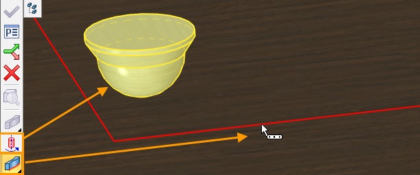
This option activates by default upon calling the command. It allows selecting a face or a set of faces to be removed when creating the shell. The parent body of the first selected face to be removed is also selected. The body is highlighted in this case and selected face is highlighted with color.
The faces selected for removal are added to the list in the provided pane in the property window on the tab [Removed].
Placing cursor in the list pane in the property window activates the option for selecting faces to remove.
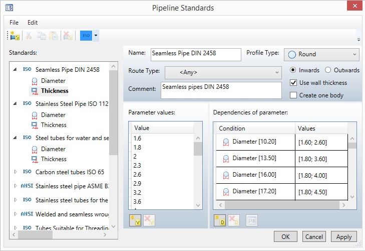
The thickness of other walls of the shell being created is defined in the input box “Thickness” of the property window. The default value is 1.
This means the walls of the faces left in the body will be 1 mm thick (the measurement units depend on the document settings).
Enlargement of the shell wall may be performed inside, symmetric and outside according to the initial body. The corresponding direction selection is performed by clicking the corresponding button in the properties window.

The wall thickness may have positive or negative value. If you specify negative value, a shell will be performed in the opposite direction.
To create a shell without removing any faces, upon entering the command switch to the automenu option:
|
<O> |
Select Solid |
This option allows selecting a solid body to create a hollow body with the specified wall thickness.


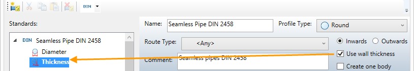
Selection of Faces with Individually Defined Wall Thickness
To define the wall thickness individually for one or several faces, select such faces with the help of the automenu option:
|
<T> |
Select Face with different wall thickness |
The option is available only when a body or removed face is already selected. The selected faces are called different and are listed on the Different tab. You can specify thickness and direction for each of the faces separately after selecting one or several faces in the list.
|
|
|
Including and Excluding Additional Faces
If it is required to include an additional body to the shell, you need to combine the existing shell and the target body using Boolean command. You should call Shell command and specify the face to delete. On the Additional tab, you should select faces that should be included into the shell. In the drop-down list select the Include faces mode. The displacement value of the additional faces is specified in the Thickness field. |
|

If there are faces of the body that should not be used during a shell creation, you should select the excluded faces on the Additional tab and enable Exclude faces mode in the drop-down list.
|
|

The following option is used to cancel selection of removed, different or additional faces.
|
<K> |
Cancel selection of Faces by pointing to them |
To cancel a selection, point the mouse at a selected face and click ![]() . Faces can also be unselected by manipulating the respective list in the property window. For this purpose, the graphic button [Delete] is provided with each list.
. Faces can also be unselected by manipulating the respective list in the property window. For this purpose, the graphic button [Delete] is provided with each list.
All faces can be unselected at once by the option:
|
<F> |
Cancel selection of all Faces |
You can confirm the operation creation as soon as the option becomes accessible in the automenu:
|
<Y> |
Finish input |
As a result, a shell body will be displayed in the 3D window.
Additional Operation Parameters
You can set additional operation parameters in the properties window using the corresponding options:
|
|
●Pierce Smooth Surface. The option allows to create a shell in the cases, when the removed face is tangent to the non-planar faces. For example, it can be a rounding (radius chamfer).
|
|
●Create Offset Body. When the flag is set an equidistant (non-hollow) body is created. The body faces will be shifted relative to the faces of the original body by the specified amount. This mode can be useful for creating workpieces with an allowance for processing.
You can use sheet bodies when you create an offset body in the Shell command.
●Keep Source Body. The option allows keeping source body and the resulting body in the scene. It may be useful when you need to preserve two models. For example, the body with an allowance and the initial body.
●Blend Convex Edges. The option allows blending convex edges formed by proportional displacement of adjacent faces. The amount of displacement determines the thickness of the resulting wall of the shell.
|
|
Blending of convex edges when the faces are shifted inward |
Blending of convex edges when the faces are shifted outward |
Only edges the thickness of the adjacent walls of which will be equal to the radius of rounding will be blended.
|
|
Edge blending with adjacent wall thickness equal to 10 (rounding radius 10) |
Edge blending with adjacent wall thickness equal to 20 (rounding radius 20) |
✍Faces extension type. The option allows you to determine which face will be ignored in case of overlapping faces.
|
|
|
|
|
Auto - movable and fixed faces do not overlap |
Extend moved – moved faces overlap fixed |
Extend fixed – fixed faces overlap moved |
Dynamic Preview
In the process of setting/editing shell parameters, the future result of the current operation is dynamically displayed in the 3D window. To increase performance, you can disable the dynamic preview by disabling the Dynamic Preview checkbox in the “Options” section of the command properties window.
Draggers Usage
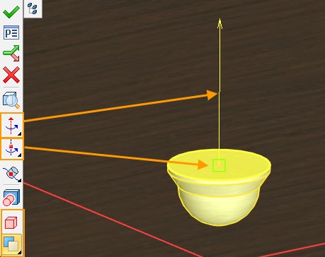
Draggers are special graphics elements, which are convenient to use to specify main numerical parameters of a shell during dynamic preview. Draggers appear after elements selection.
There are two draggers types for the operation:
●Dragger for specifying general shell thickness appears upon a body or removed face selection on the largest (not selected) face of the model;
●Draggers for specifying thickness of different faces.
Draggers may specify face offset both inward and outward. They are synchronized with the parameters of the direction of the faces offset.
Using draggers while working with a large number of objects on a computer of low performance may cause a significant system slowdown. In this case, you can disable draggers using the Use draggers option in the “Options” section of the properties window.
Troubleshooting
When creating “Shell” operation, the system may fail to calculate the result in some cases. A reason for a failure could be particulars of the source body geometry. Let's review most typical situations:
1.Degenerate faces. When creating an offset, some faces may disappear. The system may handle some of the cases. However, if there are too many such faces, or several adjacent faces disappear, the system outputs an error.

2.Offset faces do not intersect. Upon creating offset faces, the system constructs intersection lines between adjacent faces for generating the resulting body. In some cases, two adjacent offset faces may not intersect.