General Parameters of 3D Elements


General Parameters of 3D Elements |
|
Similar to the 2D elements, each of the 3D elements has a certain set of parameters. Some of these parameters are common to all objects in the system, regardless of their dimension; others are specific to the 3D elements, while yet other parameters are only inherent to specific types of objects. To skip the description of the general parameters in each chapter, we will do it once, while reviewing only the specific parameters in the respective chapters.
"Common" tab
The dialogs of parameters of all 3D operations contain the identical tab called “General”. The set of parameters of this tab includes nonspecific parameters of the given operation and parameters of visualization of the Body in the generation of which this given operation is involved.
Parameters of visualization of a 3D image (level, layer, material, image quality) are specified for the entire Body. Therefore, the values of the parameters of visualization on the “General” tab will be identical for all operations that are included into the history of creation of the given Body.
When viewing the properties of the Body itself (the “Properties” command in the context menu of the tree of the 3D model), the dialog of parameters of the last, in the history of the given Body, operation is.
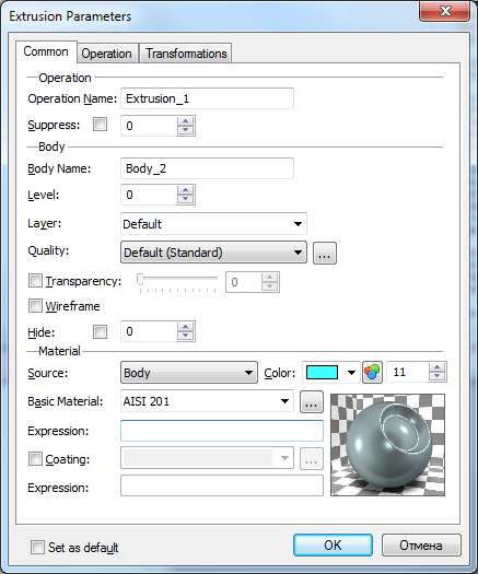
The “Operation” group:
●Operation name – the name of the 3D operation for which the dialog of parameters is invoked;
This name is used for selection of the desired element from the list. The user can specify the name independently. In this case the system only keeps track of the uniqueness of the entered name. If the user does not specify the name, the system generates its own name consisting of the name of the element and the element's identification number. The default names for each type of elements are described in the file Opernames.ini.
●Suppress – this option is responsible for exclusion of the given operation from 3D model recalculation. The suppressed operation is not shown in the 3D scene. It is advantageous to use the given parameter during the stage of forming the individual parts of complex assemblies. The user can temporarily suppress the elements that have already been worked on and work with those elements which are required for further constructions. A real variable can be used as the value of the given parameter. The operation will be suppressed if the value of this variable is not equal to zero;
The “Body” group:
●Body name. The name of the Body in generation of which the given operation takes part.
●Level, Layer – common to the system parameters of the Body.
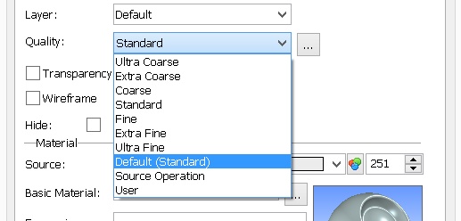
Quality. Parameter that defines the quality of 3D images of the Body. It defines the degree of discretization of the model into the grid of planar triangular faces when showing the image in 3D window. From the drop down list it is possible to choose the predefined sets of parameters that define the quality of the mesh:
●Ultra coarse; ●Extra coarse; ●Coarse; ●Standard ●Fine; ●Extra Fine; ●Ultra Fine; |
|
●Default (Standard) – the values for model discretization parameters are taken from the “ST: Set Document Parameters” command (the “Image quality” parameter on the “3D” tab);
●Source operation – the values for model discretization parameters are taken from the parameters of the operation that is a parent with respect to the operation indicated in the given dialog of parameters
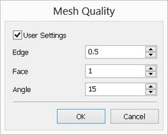
User-defined – the values for model discretization parameters are specified by the user. Additional button […] invokes the dialog window for specifying the user-defined values of model discretization parameters (in units of a model). In the mesh parameters dialog it is possible to specify your own values of: allowance by edge, face precision and angular allowance. |
|
The higher quality of model image increases the number of planar faces and slows down the work for large models or insufficiently productive video-cards. It is recommended to make the model image quality as low as possible.
When reading the models of the previous versions, the system automatically selects new parameters of the quality. In certain situations the automatically assigned quality can turn out to be lower or higher than the expected one. In these cases it is recommended to change it manually by selecting the corresponding value of the quality in the parameters of the document (the “3D” tab in the Customize > Status Document Parameters command) or in the parameters of the Body. The number of triangles that a specific model is discretized into, when a particular value of the mesh quality parameter is specified, can be determined with the help of the “Display graphics performance data” option in the “Graphic system parameters” dialog. This dialog is invoked by pressing the “Graphics parameters…” button on the “3D” > “Graphics Settings” tab of the Customize > Settings Options command.
●Transparency. The flag, scroll bar and the field for editing the transparency value.
●Wireframe. When using this option, the body will be displayed in the wire-frame view mode.
●Hide – this option allows us to hide the Body in the 3D scene without excluding it from the recalculation of the model.
All parameters in the “Body” group are accessible for editing only in the case when the current operation is uniquely linked with the Body. If the given operation generates several different Bodies, parameters of the given group are not accessible.
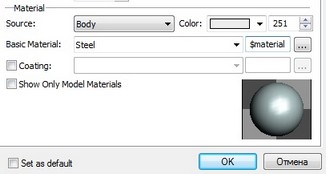
Parameters of the “Material” group allow us to make virtual models appear like a real product when the “Shading with Materials” visualization mode is used:
●Source — parameter which determines from where the material is taken. The possible variants are:
Body. Parameters are specified in the current Body;
Source operation. Parameters are inherited from the source operation;
Current operation. Parameters are specified in the current operation. This option is introduced to provide compatibility with the previous versions;
●Color — color of the Body in the modes “Wireframe view”, “Shading”, “Viewing with removal of invisible lines”, “Viewing with precise removal of invisible lines”.
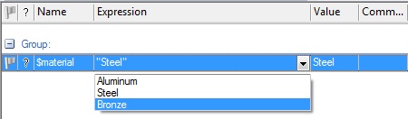
●Basic material - material of the Body used for evaluation of the mass inertial characteristics and engineering analysis. It is also used for determining parameters of the model view in the 3D window if an additional material of the “outer cover” is not specified. It can also be specified as a text variable.
The value of such a variable constitutes the name of an existing material. When the variable is created directly in the window of the operation's parameters, the list of possible values of the given variable is created simultaneously. This list contains all materials used in the given model. |
|
If the model is used as a 3D fragment, the material of the fragment can also be controlled with the help of such a variable.
●Coating. Additional parameter for specifying parameters of the model view in the 3D window. It allows us to specify the material that is different from the main material to use it for the purpose of visualization. In this case, the main material will still be used for engineering calculations. To specify the material of the outer cover, the corresponding flag must be enabled. The material can also be specified as a text variable.
●Show only materials of a model – auxiliary parameter that controls the structure of the materials selection list when working with the dialog of operation's parameters. If this flag is enabled, the “Name” list will show only those materials which were used in the given model. Material – is also an element of the 3D system. It contains the list of characteristics of the real material which we encounter in real life. The “material” element has parameters such as density, reflexivity, transmittivity and so on. All this is described in more detail in the special chapter devoted to this issue.
General” Tab in dialogs of parameters of 3D construction elements
In the dialogs of parameters of 3D construction elements on the “General” tab there are the following common parameters:
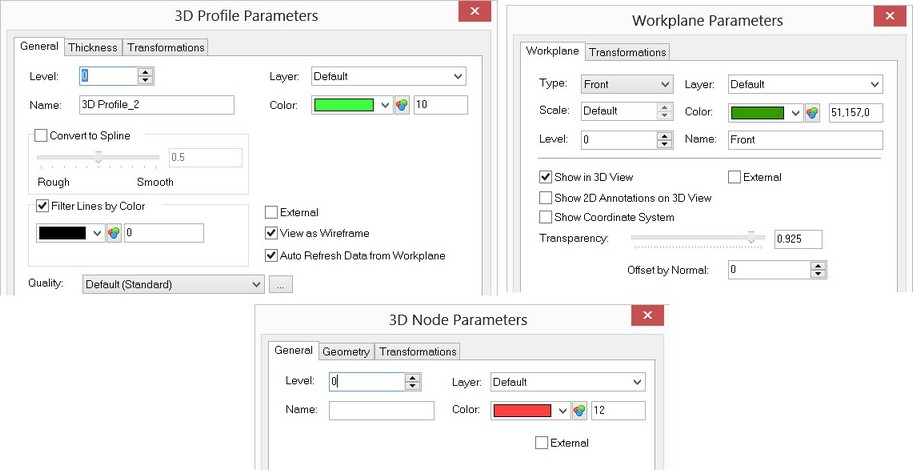
Level. The value of the visibility level. It allows controlling the visibility of various elements.
Color. Element color.
Layer. The name of the layer to which the element belongs.
Name. If the user skips assigning a name, then the system generates its own name consisting of the element type and a through ID number. The default names for each element type are described in the file Opernames.ini. For example, the generated workplanes names are: Workplane_0, Workplane_27, etc.
"Transformation" tab
This tab contains information about the current object transformations.
A set of various transformations can be defined for any 3D object that will modify its original position in the space (the detailed description of handling transformations is available in the chapter "Transforming 3D elements").
"Offset/Rotation"-type transformation is defined by default for any 3D element with zero parameter values. It is initiated automatically at the element creation. A number of additional transformations are automatically defined for 3D fragments and Parts.
Additional transformations can be defined by two ways: by using the command "3EG: Transform Element" or directly on the discussed tab of the object parameters dialog box. The two ways are equivalent. The transformations defined by the command "3EG: Transform Element" will be displayed and accessible for editing in the parameters dialog box of the current object. Vice versa, any changes done to the set of a 3D object transformations in the tab "Transformation" of the parameters dialog box will be accessible for future editing in the command "3EG: Transform Element".
The main difference between using the specialized command and the parameters dialog box is as follows. When creating a new transformation via the parameters dialog box, the reference elements of the transformation (axis, vector, point, coordinate system referenced by the transformation) are defined by the system automatically. When working in the command "3EG: Transform Element", you can define arbitrary reference elements manually.
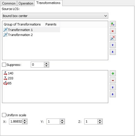
The list of the existing transformations is displayed in the upper-left corner of the tab. The rest of the fields display the parameter values of the current (selected in the list) transformation. The buttons next to the transformations list allow defining new transformations (![]() ), delete the existing ones (
), delete the existing ones (![]() ), move the transformations in the list up
), move the transformations in the list up ![]() and down
and down ![]() . The order of transformations in the list defines the sequence in which these transformations are applied to the object.
. The order of transformations in the list defines the sequence in which these transformations are applied to the object.
The entry beneath the list displays the name of the selected transformation. It can be modified by entering a new value here.
Besides the geometrical parameters (offsets, rotations, scale), the additional parameters can be defined for the selected transformation:
Suppress. This parameter allows temporary excluding of the transformation from the object position calculation. A numerical variable can be used as the value of this parameter. The transformation will be suppressed, if the variable value is not zero.
Only for exploded view. With this flag set, the transformation will be taken into the account in the exploded state only (the command "3VX: Exploded View").
The general parameter "Apply exploded view transformation of base elements" also affects the behavior of the current 3D object in the exploded state. With the flag set, all exploding transformations defined for the parent elements of the 3D object will be applied to this object as well. Consider, for example, a nut and bolt subassembly. The nut will first be subjected to the bolt exploding transformation, and then to its own. With the flag cleared, the object's position in the exploded state is defined by its own transformations only.