Working with the 3D View Window


Working with the 3D View Window |
|
The 3D view window (the 3D window) is one of the main system tools for working with the 3D model. It is used for the 3D scene rendering. The 3D window serves for viewing the model being created, as well as for selection of 3D objects for performing various manipulations with them (getting information about the selected object, editing, using as a base reference when creating operations and 3D constructions).
What is "3D Scene"?
3D scene is the entirety of all 3D objects (3D bodies and 3D constructions) that are present in the model. The size of the 3D scene is determined by the minimal cube fitting all 3D elements. When determining dimensions of the cube, the invisible 3D objects hidden from display by various methods are also included in the account.
Objects in the 3D scene are viewed using cameras. The camera that feeds the image in the 3D window, is called the active camera. By default, only the system camera is present in the model, which is located beyond the limits of the 3D scene. This is what is normally used to view the 3D scene. In most cases, just the system camera is enough for working with the 3D model. The position and orientation of the system camera can be controlled. The system camera cannot be deleted, neither can it be moved inside the 3D scene (the distance from the camera to the center of the 3D scene cannot be made less than half the 3D scene size).
In certain cases (for example, when surveilling inner parts of complex 3D models or when creating animation clips) the capabilities of just the system camera may not suffice. In such cases, the user can create and use one's own cameras for setting up a view in the 3D window. Custom cameras are attached to local coordinate systems (LCS). An LCS position determines a camera position. The respective section of this chapter is devoted to working with custom cameras.
The Methods of the 3D Scene Rendering
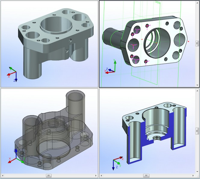
Visualization of 3D objects in the 3D view window can be done by various means (as a wireframe model, as solids, etc.). The 3D objects themselves do not change in this case, rather, their rendering method is changing.
There are the following visualization methods:
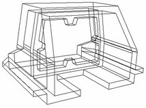
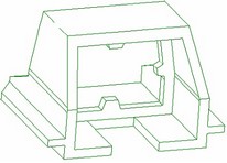
● Wireframe - all three-dimensional bodies are displayed as a framework of their member edges. The method is convenient in that the background elements are not obstructed by the foreground ones. One can also see the objects located inside the body. This property is used when selecting construction elements for performing operations.
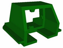
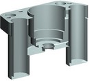
● Shading - all three-dimensional bodies are rendered in a specific color defined for each body.
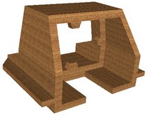
● Rendering - all three-dimensional bodies are rendered with an account for the specifics of the selected material, whether for the entire body or assigned to a particular face.
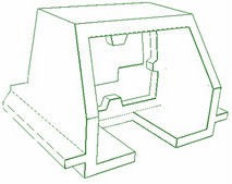
● Wireframe with hidden lines removal - the 3D window displays the 3D model wireframe without invisible lines. The fast algorithm of finding line visibility is used.
● Wireframe with precise hidden lines removal - the wireframe model is displayed in the current position, without the invisible lines. This mode can be used only with the orthographic (parallel) projecting method.
The selected visualization method is applied by default to all elements of the 3D scene.
Note that a visualization method is a characteristics of the 3D window, and does not depend on the camera used (whether the system or a custom one). That means, the visualization method assigned to a 3D window is maintained even when switching the active camera (that is, the one used at the moment for viewing the 3D scene).
The wireframe mode can be also assigned to individual 3D Bodies or operations. Such 3D object will be rendered in the wireframe mode always, regardless of the visualization method set for the 3D window. The sticky wireframe mode can be turned on by adjusting parameters of the respective 3D Body or 3D operation (see the chapter "General parameters of 3D elements").
For shading and shading with materials it is possible to additionally enable the mode of semitransparent viewing. When using the semi-transparency, the 3D model is displayed according to the rules of the main method of visualization but all faces of the bodies in the 3D scene become semitransparent.
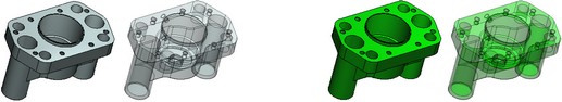
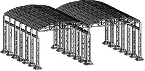
Shading with materials |
Shading with materials and semitransparency |
|
Shading |
Shading and semitransparency |
Transparent view can be enabled individually for any Body of the model. But such a Body will be displayed as transparent only when the mode of shading with materials is used. The transparent view can be enabled in the dialog of parameters of the Body or in the dialogs of parameters of operations included into the history of creation of the given Body (see the “General Parameters of 3D Elements” chapter).
Moreover, there is a possibility to make transparent the individual faces of Bodies. This can be done with the help of the “3AM: Apply material” command. Transparency of faces is also visible only in the mode of shading with materials.
Working with the System Camera for Surveilling of the 3D Scene
Projecting Method
The appearance of the 3D scene in the 3D view window depends, besides the specified visualization method, on the projecting method used by the system camera. The projecting method determines, how the camera will be showing objects in the 3D scene: without respect to the distance from the view point and the field of view angle - by the orthographic (parallel) projection, or by accounting for those parameters - the perspective projection.
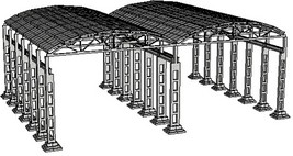
|
|
Orthographic (parallel) projection |
Perspective projection |
A projecting method, unlike a visualization method, is a characteristic of the particular used camera, rather than the 3D window. When switching the active camera (for example, switching from the system camera to a custom one), the image generation in the 3D window will account for the new active camera projecting method.
Controlling the System Camera. Rotating (Spinning) and Moving a Camera
Initially after opening the 3D window, the system camera is located at the distance providing visibility of all elements of the 3D scene (that is, all 3D constructions and 3D Bodies present in the model). To view the 3D scene, you can rotate (spin) and/or move it arbitrarily, zoom in and out, change the orientation and view direction, as well as scale the image in the 3D window.
As the user watches the 3D window in the process of spinning (rotating) and moving the system camera, one feels as if the 3D scene itself is moving, rather than the camera. Therefore, when describing 3D model handling in the future, we will often refer to the process of rotating (spinning) and moving the system camera as the 3D scene rotation.
Camera's center of rotation
Rotating the image in the 3D window with the default system camera active is achieved by moving the camera about the scene center. If necessary, the center of rotation can be changed. The following can be selected as the new rotation point:
● An operation's center of mass;
● An arbitrary point in the 3D scene. The center of rotation will be the intersection of the ray passing through the selected point perpendicular to the screen plane with the face or edge (in the case of the wireframe display) of some 3D Body or any 3D construction element nearest to the camera. If the ray does not cross any of the 3D objects, then the center of rotation stays unchanged;
● The 3D scene center (whenever necessary to return to the original center of rotation).
System camera rotation modes
There are the following system camera rotation modes:
● Free rotation. This mode is preset by default. In this mode, a 3D camera can be rotated in an arbitrary direction about the rotation center;
● Rotation about one of the axes of the coordinate system located at the center of the camera's rotation. the direction of the rotation coordinate axes can be:
- Coincident with the direction of the global coordinate system axes (rotation with respect to the global coordinate system),
- Defined by the coordinate system of the 3D window itself (rotation with respect to the window coordinate system) - one axis being directed perpendicular to the screen plane, the two others lying in that plane (one - vertically, the other - horizontally).
Automatic Rotation
Automatic Rotation can be performed in any of the above-listed modes of the system camera rotation. To activate the automatic rotation mode, specify the direction and speed of rotation. Before terminating the automatic rotation mode, the system camera rotation command with such parameters will be repeatedly sent to the 3D window, which add the inertia effect to the 3D scene rotation.
Auto-Resize
Auto-Resize is a 3D window mode, when the system camera's parameters are automatically updated upon each 3D model regeneration, so that the entire 3D scene is visible.
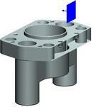
Clip Plane
Use a clip plane as a handy visual examination tool for inner body parts. It is a plane, which can move along the specified direction and "slash" objects in the scene. The cut-off part of bodies is not displayed. No new bodies are created in this case. As the camera rotates, the orientation of the clip plane changes together with the changes in the scene position.

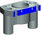
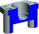
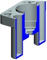
The resulting body section is filled with blue color (this allows us to examine the shape of the section).
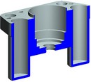
The clip plane is not displayed by default. If necessary, the clip plane can be made invisible. It will appear as a small rectangle indicating the position and orientation of the clip plane.
Light Sources
Illumination of bodies in the 3D scene is provided by light sources. Light sources can be divided into two main types:
● Stationary sources created by the user in the command "3L: Create Light Source". Such light sources are independent of the used camera and its position. How to create stationary light sources will be described in details in the "Light sources" chapter of this manual;
● Dynamic light sources, "mounted" on the active camera. The position of such light sources is defined relative to the active camera. When moving/rotating the active camera, the light sources will be also changing their position.
Dynamic light sources, as well as the visualization method, are characteristics of the 3D window, that does not depend on the used camera (whether the system or a custom one).
By default, there are two light sources in the 3D window attached to the active camera, an ambient light source (which uniformly illuminates the entire space of the 3D scene) and a directional source of white light, located on the camera. If necessary, the user can change their parameters (color, intensity, and, for a directional light - the position with respect to the camera), as well as manually create additional dynamic light sources.
Creation and editing of light sources attached to the active camera is done in the special 3D view parameters dialog. You can also specify there the background color of the 3D window (the background color does not depend on the light sources present in the 3D window). The user can select any color as the background according to one's preferences. You can use a transitional background color (with a smooth change from one color to another).
Working with Multiple 3D Windows
When working with a 3D model, the user can open several 3D windows simultaneously. Individual parameters can be assigned to each of the open 3D windows: the visualization method, the orientation and view direction of the active camera, the background color and number of light sources on the active camera, the image scale, etc.
Using 3D Views
You can use the system preset 3D views for quick setup of a 3D window. 3D View is a set of information about a 3D window, including information about the parameters of the used camera, about the light sources attached to it, the current rendering method, etc.
When loading one of the 3D views stored in the system, into the current 3D window, the 3D window is automatically set up according to the data of this 3D view.
The user can edit 3D views present in the system, adding to those unique sets of data about the state of the 3D window. 3D views are handled in the special 3D view parameters dialog.
Managing 3D Window
Use the commands located in the "View" textual menu to manage the 3D window and the 3D scene display in it. Commands are grouped according to their purpose. Some of the commands are also available on the same-name "View" toolbar.
There is yet another way to call these commands. Point the mouse to a free space of the 3D window and right-click ![]() . The coming up context menu will contain all commands for managing the 3D window. The state of the context menu icons informs you about which mode of a particular command is currently active.
. The coming up context menu will contain all commands for managing the 3D window. The state of the context menu icons informs you about which mode of a particular command is currently active.
Defining a Visualization Method
To define a visualization method, use the commands:
Keyboard |
Textual Menu |
Icon |
<3VW> |
"View|Render|Wireframe" |
|
<3VS> |
"View|Render|Shading" |
|
<3VD> |
"View|Render|Render" |
|
<3VH> |
"View|Render|Hidden Line Removal" |
|
<3VZ> |
"View|Render|Precise Hidden Line Removal" |
|
<3VM> |
«View|Render|Semitransparent View» |
|
Every method uses additional parameters. You can define those parameters in the 3D view parameters dialog described in the respective section of this chapter.
Rotating (Spinning) and Panning the 3D Scene
When working with a 3D model, the most commonly used is the free rotation mode; therefore it is preset in the 3D window by default. The camera can be moved around the rotation center by simply dragging the mouse with the ![]() depressed within the 3D window.
depressed within the 3D window.
You can also use the keyboard for rotating the 3D scene. The <Left>, <Right>, <Up>, <Down> keys make the 3D scene rotate in the respective directions. You can rotate the camera about its own axis using the <PageUp>, <PageDown> keys. When the <Ctrl> key is pressed, all these keys work in the fast rotation mode.
The speed of rotation for the normal and fast modes is set up in the "Customize|Settings" command on the "3D" tab.
By using ![]() while holding down the <Ctrl> key, you can move the camera in the plane parallel to the screen. In this way, the center of rotation moves together with the camera.
while holding down the <Ctrl> key, you can move the camera in the plane parallel to the screen. In this way, the center of rotation moves together with the camera.
To change the image scale ratio, use ![]() with <Shift>. By moving the pointer up the screen, you zoom out of the image, by moving down - zoom in.
with <Shift>. By moving the pointer up the screen, you zoom out of the image, by moving down - zoom in.
This process is similar to the function of a real camera. The camera, however, stays still. Only the focal length of its objective lens changes.
If your mouse has a wheel, then you can control the degree of zooming on the image by spinning the wheel. Dragging the mouse with the wheel depressed moves the camera in the plane parallel to the screen plane.
Rotation about one axis can be activated by using one of the following commands in the "View|Rotate" textual menu or the same-name item of the context menu in the 3D window:
Keyboard |
Textual Menu |
Icon |
<3RX> |
"View|Rotate|Around X axis" |
|
<3RY> |
"View|Rotate|Around Y axis" |
|
<3RZ> |
"View|Rotate|Around Z axis" |
|
Calling any of those commands results in assuming the mode of rotating about the selected axis. Switching the axis, about which rotation is performed, is done by the same commands. You can judge which axis is currently used by the state of the respective icons in the textual or context menu. Orientation of the rotation coordinate axes is determined by the state of the command "3RS: Toggle between 3D Scene Rotation Modes":
Keyboard |
Textual Menu |
Icon |
<3RS> |
"View|Rotate|Screen coordinate system" |
|
When this command is active, rotation occurs in the window coordinates, when off - the orientation of the rotation coordinates coincides with the global coordinate system. This command activates automatically when switching to rotation about one axis. Therefore, by default rotation occurs in the window coordinates. You can judge the state of the command by its icon in the textual or context menu.
Rotating the 3D scene about one axis is done in the same way as in the free rotation -- using ![]() or the keyboard. The difference will be only in that rotation will occur only about one selected axis of the camera's rotation coordinate system upon any mouse movement or control key strikes.
or the keyboard. The difference will be only in that rotation will occur only about one selected axis of the camera's rotation coordinate system upon any mouse movement or control key strikes.
To return to the mode of the free camera rotation, use the command:
Keyboard |
Textual Menu |
Icon |
<3RF> |
"View|Rotate|Free" |
|
The mode of fixed direction of the sight is enabled with the help of the “3RL: Fix direction” command. It can be invoked from the text menu “View|Rotate” or with the help of the context menu in the 3D window:
Keyboard |
Textual Menu |
Icon |
<3RL> |
«View|Rotate|Fix» |
|
When this mode is enabled, the direction of the sight gets fixed, i.e., rotation of the 3D scene is impossible. But it is possible to scale and translate the contents of the 3D scene. This setting is saved in the current document and active during subsequent sessions of work with it.
To turn off the mode of the fixed direction, it is required to select any other mode of rotation of the 3D scene.
The command “3RP: Rotation panoramic”:
Keyboard |
Textual Menu |
Icon |
<3RP> |
«View|Rotate|Panorama» |
|
In this mode the plane of the Z-axis is fixed. This mode creates the effect of viewing the room-scene with a video-camera which cannot be inclined (the Z-axis in this case plays a role of the vertical axis of the room). The mode of the panoramic rotation can be useful when working with the models of buildings, furniture, interiors etc.
Use the following additional commands for quick manipulations with the orientation and scale of the 3D scene display:
Keyboard |
Textual Menu |
Icon |
<F3> |
"View|Scale|Zoom Area" |
|
<Ctrl><Shift><PgUp> |
"View|Scale|Zoom In" |
|
<Ctrl><Shift><PgDn> |
"View|Scale|Zoom Out" |
|
<Ctrl><Shift><Left> |
"View|Scale|Pan Left" |
|
<Ctrl><Shift><Right> |
"View|Scale|Pan Right" |
|
<Ctrl><Shift><Up> |
"View|Scale|Pan Up" |
|
<Ctrl><Shift><Down> |
"View|Scale|Pan Down" |
|
<Ctrl><Shift><Home> |
"View|Scale|All Objects" |
|
<Ctrl><Shift><End> |
"View|Scale| Maximize |
|
"View|Scale|Actual Size" |
|
|
"View|Scale|Previous" |
|
A detailed description of working with these commands is available in the chapter "Document Management".
Defining the Center of the 3D Scene Rotation
To define the center of camera rotation, use the command "3RC: Select Center Of Rotation":
Keyboard |
Textual Menu |
Icon |
<3RC> |
"View|Rotate|Set center of rotation" |
|
After the call, the current camera rotation center appears on the screen as a crosshairs. The following options become available in the automenu:
![]() <P> Select any point as rotation center
<P> Select any point as rotation center
![]() <O> Select center of solid as rotation center
<O> Select center of solid as rotation center
![]() <D> Select center of scene as rotation center
<D> Select center of scene as rotation center
To select the center of mass of a 3D operation as the center of rotation, simply activate the option ![]() , and then select the desired operation. The crosshairs marking the rotation center will move to the center of mass of the selected body.
, and then select the desired operation. The crosshairs marking the rotation center will move to the center of mass of the selected body.
The option ![]() allows specifying an arbitrary point as the center of rotation. For this, after selecting the option, simply pick the desired point (using
allows specifying an arbitrary point as the center of rotation. For this, after selecting the option, simply pick the desired point (using ![]() ) in the 3D window. If the ray passing through the given point perpendicular to the screen plane crosses some 3D object, then the center of rotation will be carried over to that point.
) in the 3D window. If the ray passing through the given point perpendicular to the screen plane crosses some 3D object, then the center of rotation will be carried over to that point.
To return the camera rotation center to the 3D scene center, simply click ![]() .
.
It is possible to define arbitrary center of rotation without calling “3RC: Select Center of Rotation” command. This can be done by pressing ![]() without releasing for some time at any object within 3D scene. The special marker-cross will appear at the specified point. This marker signals about setting the position of the new temporary center of rotation. After finishing the rotation (when mouse button is released) center of rotation returns to the original position.
without releasing for some time at any object within 3D scene. The special marker-cross will appear at the specified point. This marker signals about setting the position of the new temporary center of rotation. After finishing the rotation (when mouse button is released) center of rotation returns to the original position.
Activating Automatic Rotation (Spinning) of the 3D Scene
To activate automatic rotation, call the command "3RA: Automatic Rotation":
Keyboard |
Textual Menu |
Icon |
<3RA> |
"View|Rotate|Automatic Rotation" |
|
To define rotation parameters, depress ![]() and, while holding it, drag the mouse in the rotation direction. After that, release
and, while holding it, drag the mouse in the rotation direction. After that, release ![]() . In that way, you define the direction and angular rotation velocity.
. In that way, you define the direction and angular rotation velocity.
The automatic rotation mode is switched off by a repeated call of the same command.
Defining the Method of Projecting the System Camera
Use the following commands to select the method of projecting the system camera:
Keyboard |
Textual Menu |
Icon |
<3VO> |
"View|Projection|Parallel" |
|
<3VE> |
"View|Projection|Perspective" |
|
Parameters of each projecting method are defined in the dialog of the current 3D view parameters. Working with this dialog is described in the "3D view parameters" section of this chapter.
Auto-Resize
To enable or disable the auto-fitting mode of the 3D scene, use the command "3VA: Auto-Resize 3D Scene":
Keyboard |
Textual Menu |
Icon |
<3VA> |
"View|Auto-Resize" |
|
The auto resize mode will be active until the second call of this command.
Working with a Clip Plane
To activate a clip plane, use the command "3CL: Enable Clip Plane":
Icon |
Ribbon |
|---|---|
|
View → Clip plane → Active |
Keyboard |
Textual Menu |
<3CL> |
View > Clip plane > Active |
A repeated command call turns off the clip plane.
To define the clip plane position, use the command "3CS: Set Clip Plane Position":
Icon |
Ribbon |
|---|---|
|
View → Clip plane → Set |
Keyboard |
Textual Menu |
<3CS> |
View > Clip plane > Set |
Calling this command sets the plane parallel to the screen and activates it.
The position of the active clip plane (the distance from it to the view point) can be modified without calling additional commands, using the ![]() together with the simultaneously pressed <Ctrl> and <Shift> keys. By moving the pointer up the screen, you move the plane "deeper" into the scene, and vise versa.
together with the simultaneously pressed <Ctrl> and <Shift> keys. By moving the pointer up the screen, you move the plane "deeper" into the scene, and vise versa.
To reveal the clip plane in the 3D scene, call the command "3CD: Show Clip Plane Position":
Icon |
Ribbon |
|---|---|
|
View → Clip plane → Draw |
Keyboard |
Textual Menu |
<3CD> |
View > Clip plane > Draw |
Repeatedly calling the command will remove the clip plane image from display.
Defining All 3D View Parameters in One Dialog
Use the convenient dialog of the 3D view parameters for quick setup of the 3D window, when you need to change its several characteristics simultaneously (for example, the visualization method, the orientation, the view direction and the method of projecting from the system camera, etc.). Some of the 3D view parameters (for example, the background color, the parameters of light sources on the camera) can be defined only in this style dialog.
To call the dialog of the 3D view parameters, use the command "3VP: Set View Parameters":
Icon |
Ribbon |
|---|---|
|
View → Properties |
Keyboard |
Textual Menu |
<PW> |
View > Clip plane > Properties |
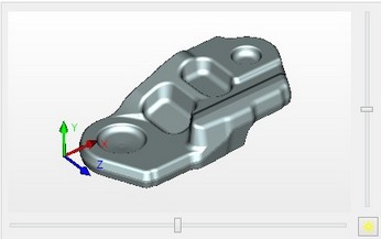
After calling the command, a dialog window appears, which contains all current 3D view parameters.
The 3D window contents preview pane is on the left-hand side of the dialog window. It displays all the same as in the master 3D window, but smaller. You can work with the image in the preview pane in the same way as with the image in the 3D view window: spin, pan, zoom. To quickly view the contents of the 3D scene, you can use the [View All] button - clicking it scales the image in such a way that all contents of the 3D scene are visible. All manipulations made in the preview pane will be also applied to the image in the 3D view window (after closing its parameters dialog).
The size of the 3D view properties dialog can be increased by moving the window boundaries with the cursor of the mouse when ![]() is being pressed.
is being pressed.
The "Show Coordinate System" flag can be used for disabling the coordinate system display in the 3D view window. The displayed size of the global coordinate system in the 3D window is defined in the command "SO: Set System Options" (the "3D" tab).
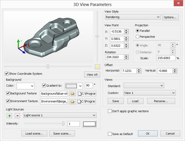
The "Background" group of parameters defines the background color of the 3D view window. To achieve a smooth transition of colors, set the "Gradient to" flag and specify two colors by selecting from drop-down lists. Clear the flag in order to make the 3D view window background monochrome. In such a case, specify just one color (the "Background color").
The “Use background texture” flag is used to enable/disable the mode of using the texture as a background of the 3D view window. When the flag is disabled the 3D view window has the color that is specified in the background parameters.
The “Use environment texture” flag is used to enable/disable the mode of using the texture as environment for 3D model. When the flag is disabled the specified texture will be suppressed.
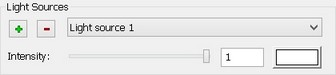
The group of parameters in the lower-left corner of the dialog window is provided to manage light sources attached to the active camera in the 3D scene. This group includes the list of dynamic light sources existing in the current 3D window, buttons for adding/deleting light sources attached to the camera, as well as control elements for defining parameters of each of the light sources.
To edit parameters of an existing light source, select this source in the drop-down list. Control elements located below the list allow changing the brightness of the selected light source (using the slider or numerically), as well as its color. The selected light source can be deleted by clicking the button The position of the selected light source with respect to the camera is defined using sliders located at the right and below the viewing pane of the 3D window contents. By default, dynamic light sources are placed directly on the camera (the sliders being positioned in the middle of their respective scales). By moving the sliders away from the center of the scale, one can move light sources right/left and up/down with respect to the camera. The |
|
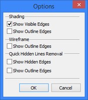
The method of the 3D scene rendering in this 3D window is defined using the "View Style" group of parameters. The drop-down list lets you select the desired method, while the ![]() button serves for defining additional parameters of each mode. Clicking this button brings up the "Options" dialog, which specifies the requirements on drawing various lines of the 3D model - edges, outline (silhouette), hidden lines - for each visualization method. The "View point", "Projection" and "Offset" groups of parameters define the view direction and the method of projecting from the system camera, as well as its distance from the center of the 3D scene. In the parallel projecting method, the camera distance is defined by the "Scale" parameter. This parameter defines the degree of zooming on the image in the 3D scene.
button serves for defining additional parameters of each mode. Clicking this button brings up the "Options" dialog, which specifies the requirements on drawing various lines of the 3D model - edges, outline (silhouette), hidden lines - for each visualization method. The "View point", "Projection" and "Offset" groups of parameters define the view direction and the method of projecting from the system camera, as well as its distance from the center of the 3D scene. In the parallel projecting method, the camera distance is defined by the "Scale" parameter. This parameter defines the degree of zooming on the image in the 3D scene.
The “Show Shades” flag is accessible only in case of another flag – “Enable Shades” from OpenGL settings of “3D” tab in “SO: Set System Options” command – is switched on. In addition the graphic board of your computer must support this functionality.
In the perspective projection, the camera distance can be defined either by the field of view angle of the 3D scene, or directly by the distance between the camera and the center of the 3D scene. All three parameters are defined numerically. Additionally, the scale and the field of view angle can be controlled using the mouse, directly in the preview pane of this dialog, similar to the way it is done in the 3D window itself when moving/rotating the camera. The "Offset" parameter defines the horizontal and vertical shift of the 3D scene center with respect to the camera.
The "Views" group of parameters, located in the lower-right corner of the dialog, serves for quick setup of the 3D window state. The "Standard" drop-down list lets you changing the view direction of the system camera according to one of the engineering drafting standards (for example, Front (elevation) View, Back View, Left (side) View, etc.). For this, simply select the desired scene orientation in the list. The "Custom" drop-down list serves for handling 3D views preset in the system.
A 3D view can be loaded (that is, the 3D window set up according to the information stored in the 3D view), saved (by writing 3D View information about the current state of the 3D window) and renamed (by simply changing the name, under which the given set of information is stored in the system). To load a 3D view, select this 3D view in the list and click the [Load] button. Clicking the [Save] button writes information about the current state of the 3D window in the 3D View selected in the "Custom" list. Clicking the [Rename…] button calls an additional dialog for defining a new name for the selected 3D view.
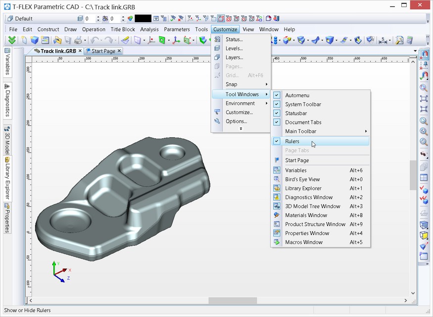
Rulers in 3D window
When working in 3D window the “Show|Hide rulers” command becomes available. This command can be invoked from the text menu «Setting|Windows». It is also available in the context menu that can be invoked upon pressing ![]() and indicating one of the toolbars.
and indicating one of the toolbars.
Rulers allow us to orient ourselves in 3D space, estimate the size of a model and distances between the elements of a model. Coordinates displayed on the rulers constitute the coordinates on the imagined plane parallel to the plane of the screen.
Also with the help of rulers of 3D window it is possible to create, in transparent mode, the new workplanes and edit location of already existing workplanes. This will be described in more detail in the “Workplanes” chapter of this user’s manual.
Working with Custom Cameras
Creating and using custom cameras will be described in details in the "Cameras" chapter. Here we will just describe general techniques of working with them.
Custom cameras are used in the cases, when the system camera is not sufficient. In such a case, the user can create one's own cameras in order to get the desired effect - for example, for surveilling inner parts of complex 3D models or creating animation clips.
The position of a custom camera is defined using an LCS. This same LCS defines the viewing direction for a custom camera. A number of parameters are defined for a camera, which define the image it yields (for example, the projecting method).
To view the 3D window from the custom, rather than the system camera, select the custom camera as the active camera of the given 3D window. This can be done in the command "3VC: Select Camera".
Keyboard |
Textual Menu |
Icon |
<3VC> |
"View|Camera|Select Camera…" |
|
After calling the commands, the "Select Camera" dialog window appears, which contains the list of all cameras present in the current 3D model. In it, select the camera that will be used for viewing (surveilling) the 3D scene.
When working with multiple 3D windows, an individual active camera can be specified for each window.
While working with a custom camera, you can use auto resizing of the 3D scene image, using clip plane, modify existing and create new light sources on the camera. How to move and spin the active custom camera is described in details in the "Cameras" chapter.
Working with the 3D view parameters dialog is similar to the described case of using the system camera, with one exception: the parameters pertaining to the active camera will not be available for editing in the dialog. In the case of custom cameras, these parameters are defined in the parameters dialog of the camera itself.
You cannot modify parameters of the active custom camera. If necessary, first select another camera as the active one (system or custom).