Setting up Parameters of a New Element


Setting up Parameters of a New Element |
|
Setting up Parameters of a New Element
The parameters can be assigned to an element being created or edited at any stage of the creation or editing. To specify an operation parameters use the Property window that supports transparent mode, or the Parameters dialog box that always requires confirmation before the input takes effect.
The parameters dialog is necessary for specifying general properties of an element or operation, such as color, level, material, etc., as well as the transformation parameters. These properties are uniformly defined for all construction elements and operations in T-FLEX CAD. The ways of handling these properties are described in details in a separate chapter of this volume. This dialog box can be used for editing operation properties without calling the operation editing command. This is especially helpful when the operation being edited is deep in the model history. Otherwise, the model rollback would be required up to the edited operation, consuming considerable time and system resources. Now, it is sufficient to select the operation of interest in the model tree and call the parameters dialog using, for instance, the context menu. The parameters dialog box may contain several tabs. The common parameters and the transformation parameters are always present and are located on their own separate tabs. These parameters are common for most of the system elements; therefore, their handling is isolated into a separate chapter of this volume. All other tabs in the dialog box repeat those in the property window. Due to this, the related chapters will describe main parameter management based on the example of the property window.
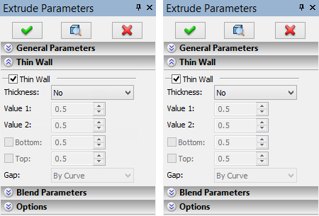
The property window is typically divided into several sections. The number of sections depends on a particular operation. Each section of the window can be expanded or collapsed using the buttons There is a field to the right of a parameter input box that displays the current parameter value. This is helpful in the cases when the parameter is defined via a variable or an expression, or else when defined “from status” (that is, uniformly for the whole document). |
|
|
Some automenu buttons are duplicated in the property window, such as the “Accept”, “Exit” and “Preview” buttons. The property window works together with the automenu. Pointing cursor at some areas of the dialog box causes activation of the respective options in the automenu, such as, say, selection options.
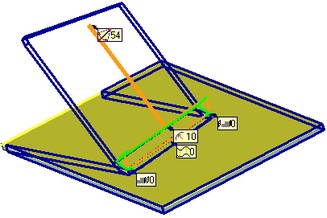
Special auxiliary graphic objects called draggers are introduced for dynamically controlling parameters of a 3D operation being defined. These appear automatically while within a command for creating or editing a 3D operation or a construction entity. Dragger manipulation is instantly reflected in the property window. The mouse-controlled dragger input defines the numeric parameter values of the operation. There can be several draggers on the scene simultaneously, providing control over various operation parameters. As an example, the “Bend” operation provides draggers for the bend angle, radius, offset and the two shifts. The “Blend” provides control over the rounding radius, etc. The values of the driven parameters are simultaneously updated in the property window of the operation being created or edited.
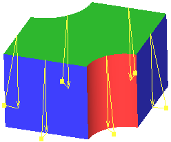
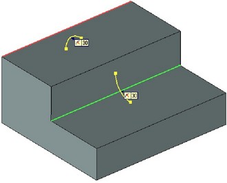
Examples of draggers in the commands “Blend Edge” and “Taper”
Marks with the current parameter values are displayed on the screen for each respective dragger. Besides the current value, a mark has an icon indicating the type of the displayed parameter. As the parameter value is modified via the property window or a dragger, the value on the mark changes dynamically.
If it's too many marks and those interfere with working in the 3D scene, you can hide them or move sideways. Hiding marks is done in the current 3D command parameters. To move a mark sideways, point the cursor to the mark's icon. Once the cursor turns to ![]() , depress
, depress ![]() and, while holding the mouse button, drag the mark image to the desired location. The moved mark will be connected to the dragger with a leader line.
and, while holding the mouse button, drag the mark image to the desired location. The moved mark will be connected to the dragger with a leader line.
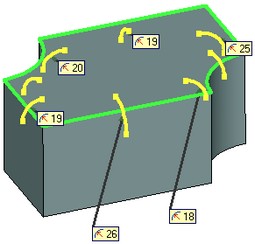
Marks serve not only to track the current parameter values, but also to modify them. To do that, click ![]() on the parameter value displayed in the mark. The mark will go into the editing mode of the parameter it controls.
on the parameter value displayed in the mark. The mark will go into the editing mode of the parameter it controls.
Preview
The following option is provided with each operation to see the result without completing the operation,
![]() <F5> Preview Operation Result
<F5> Preview Operation Result
This option becomes accessible once the required parameters of the operation have been defined. Once this option is set, the displayed body starts to reflect the operation per its current parameters. In the case of satisfactory results, complete the input by pressing the icon ![]() . Otherwise, turn off the preview option by pressing on the icon once more, and adjust parameters as desired.
. Otherwise, turn off the preview option by pressing on the icon once more, and adjust parameters as desired.
Editing Parameters of Operations with the Help of Draggers Outside of Commands
When selecting a Body in 3D window, in addition to the Body itself the draggers of the operations taking part in its formation are marked on the screen. The draggers allow us to directly edit parameters of the operations that form the Body in a transparent mode without entering into the editing command.

Draggers of External Variables
To specify the values of external variables of a 3D model, the user's draggers can be created.
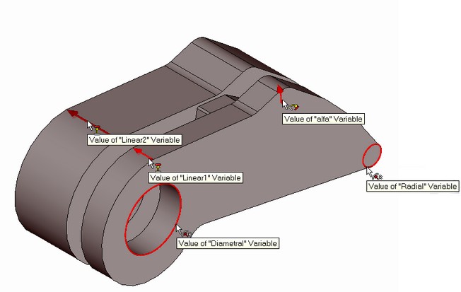
Draggers of external variables can be used in two ways:
●to change parameters of the model in the scene. The command of controlling the draggers visibility in the scene – «Show/hide draggers» is added to the toolbar of objects visibility control in the scene;
●to change values of external variables on the fragment upon insertion of the model into the assembly.
To create draggers it is required that the external variables that control parameters of the given model be present in the current 3D model.
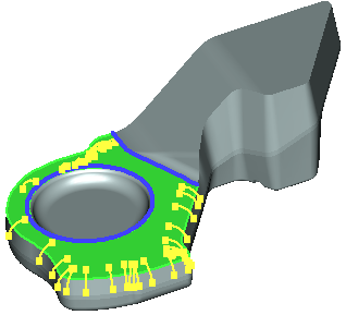
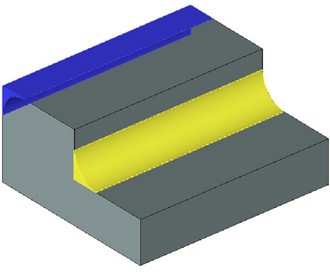
Preview of Operation Result
In the commands for creating and editing the modifier operations, there is an additional mode allowing a user to see the changes produced in the model by the current operation:
![]() <Ctrl+F5> Preview Solid Changes
<Ctrl+F5> Preview Solid Changes
In this mode, the parts of the volume which will be added to the source body are shown with a yellow color, and the parts of the volume which will be removed from the source model are shown with a blue color.
Similar to the option for previewing, the option ![]() is available only when all necessary elements for creating operation have been specified.
is available only when all necessary elements for creating operation have been specified.