Local Coordinate Systems


Local Coordinate Systems |
|
A local coordinate system (LCS) is an auxiliary 3D construction element, that allows positioning 3D objects in the space. LCS's are widely used in 3D modeling, for example, for building 3D assemblies, copying 3D bodies, defining transformations, etc.
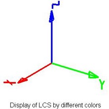
An LCS is displayed in the 3D scene as three named arrows, indicating the directions of the axes of the given coordinate system. The point where the arrows drawing is the LCS's origin. The size of an LCS's image is controlled in the command "ST: Set Document Parameters", on the tab "3D-View", by the parameter "Size-LCS".
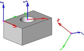
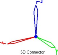
On the basis of the LCS it is possible to create special 3D construction elements of the T-FLEX CAD — 3D connectors. 3D connectors are used for attaching fragments when creating 3D assemblies. They represent themselves the LCS of a special type which are able (besides performing the function of attaching the fragments) to pass the values of the variables of one 3D fragment into another fragment. The use of the 3D connectors significantly simplifies positioning of the parts and matching of the fragment parameters when designing the assemblies.
The image of the 3D connector in the 3D window is analogous to the image of the standard LCS, but the axes are marked with “volume” arrows.
Steps of creating LCS
Generally, an LCS creation includes the following steps:
1. Selecting LCS origin. A local coordinate system is created in the selected origin point with the same axis orientation as the global coordinate system.
2. Selecting X-axis direction. X-axis of the LCS resulting from the previous step, is reoriented in the specified direction.
3. Selecting Y-axis direction. Y-axis of the LCS resulting from the previous step, is reoriented in the specified direction.
4. Selecting surface for additional reorientation. The LCS resulting from the previous step, is reoriented in such a way, that its X-axis becomes pointing at the nearest point on the specified surface.
5. Selecting tangency surface. The LCS resulting from the previous step, is reoriented to achieve tangency with the specified face/surface.
6. Selecting required LCS transformations. The LCS resulting from the previous step, is rotated about its axes.
Some steps can be skipped. The only required action is selecting the origin of the LCS.
7. Specifying additional non-geometrical characteristics of the LCS (associated elements, visibility in the assembly, etc.).
Defining the origin of the LCS
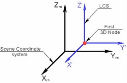
The origin of LCS is defined by a 3D point. An LCS is created in the specified 3D point with the axes orientation (X', Y', Z' on the diagram) coinciding with the orientation of the axes of the global coordinate system.
Defining X-axis direction of LCS
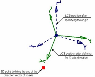
To define X-axis direction of the LCS being created, specify either the direction vector itself or its 3D end point (the first point of the vector is the 3D point defining the origin of the LCS). As a result, the coordinate system is reoriented in such a way, that the X-axis assumes the desired position.
The rotation axis is defined as follows: a plane is constructed through the two positions of the X-axis –the old (resulting from the previous step) and the new (defined at the current step). The normal to this plane, passing through the origin of an LCS, is exactly the rotation axis.
Defining Y-axis direction of LCS
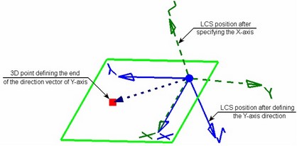
The Y-axis direction is defined, as in the case of the X-axis, either the direction vector itself, or by its 3D end point (the first point of the vector is the 3D point defining the origin of the LCS).
The step is performed only upon the condition of completing the previous one, which is the selection of the X-axis direction. You cannot define the Y-axis direction without specifying the X-axis direction.
The vector of the Y-axis direction does not define the Y-axis direction, rather, the position of the plane XY, in which this axis must be located. The plane will pass through the X-axis of the LCS and the specified vector of the Y-axis direction. As a result, the X-axis of the LCS maintains its position, and the Y-axis is located in the specified plane at the angle of 900 to the X-axis. The direction of the Z-axis is defined automatically based on the X and Y axes.
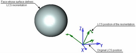
Reorienting X-axis of the LCS towards the nearest point on the selected surface
Reorienting the X-axis of the LCS towards the nearest point on surface is used in the case, when it is impossible to achieve the desired position of the LCS by selecting vector of the X-axis direction.
Upon selecting the reorientation surface, the LCS being created is reoriented in such a way, that its X-axis is directed towards the point of the selected surface nearest to the origin of the LCS.
The reorientation surface can be represented by a worksurface or plane. You can also select a face, flat edge or a simple body (a body, all whose faces lie on one surface). In this case, the reorientation surface is represented by the geometrical surface underlying the selected element.
Reorienting an LCS is done similar to rotating an LCS at the time of defining the original X-axis direction.
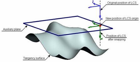
Snapping LCS to tangency point on surface
Snapping LCS to tangency point on a face allows adjusting the position of the origin of the LCS being created.
The new position of the origin of the LCS is defined as follows: an auxiliary plane is constructed parallel to the plane YZ LCS and tangent to the selected surface. If there are several such planes, the nearest to the origin of the LCS is selected. The intersection point of the auxiliary plane and X-axis will become the new origin of the LCS.
The tangency surface is defined in the same way as the reorientation surface. To do this, you can select a worksurface or plane, face, flat edge or a simple body. However, limitations are applied in this case:
● If a plane is used as the tangency surface (a workplane, and underlying plane of a flat face or flat edge), it must be perpendicular to the X-axis of the LCS;
● If the tangency surface is defined by a cylindrical face – the axis of the cylinder must be perpendicular to the X-axis of the LCS.
Modifying axes orientation of LCS
To modify axes orientation of an LCS, you need to use stepwise rotation of the LCS about any of its axes. In one pass, the LCS is reoriented by 900 about the selected axis. Additionally, a provision is made for cyclical rotation of the axes of an LCS. The result of the cyclical rotation is shown on the diagram.
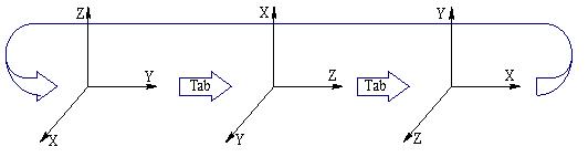
If both ways of modifying axes orientation of an LCS are combined together (rotation about one axis and cyclical rotation), then the specified rotations about the specifics axes are performed first, and the cyclical rotation follows.
Additional Characteristics of LCS
In addition to geometrical parameters defining location and orientation of the axes of the local coordinate system, for the LCS it is possible to specify a series of additional characteristics which are necessary when using the LCS for attaching 3D fragment in the assembly.
Visibility of LCS in Assembly
Four visibility modes can be specified in the assembly drawing for the LCS being created in the 3D fragment document:
-Invisible in assembly. This mode is set on by default. The LCS created in the fragment document, will be not accessible in the assembly document. The LCS of the fragment will be visible neither in the 3D window, nor in the LCS list of the assembly model;
-Visible in assembly on one level. This LCS will be visible in the assembly model and available for snapping to it under condition that the fragment containing this LCS is a fragment of the first nesting level. The location of such coordinate system is determined by the location of the 3D fragment. This LCS can be used for attaching other 3D fragments, and also for creating any construction elements and operations of the assembly model;
-Visible in assembly on all levels. The LCS will be visible in the assembly document and accessible for snapping to it for any nesting level of the fragment in the assembly;
-Externally invisible in assembly, but available for snapping to it. This mode is used most frequently for 3D connectors operation. In this mode, by default, the LCS of the fragment is not displayed in the 3D window of the assembly model. However, upon bringing the cursor to the LCS (or to its associated elements) the LCS will be “shown” in the assembly model and it will be possible to select it for snapping. Such LCS is also displayed in the list of the local coordinate systems of the assembly (with gray color, as invisible).
Visibility of Fragment’s LCS in Assembly
The following types of LCS can be visible in the model tree of an assembly: “On one level”, “On all levels”, “Connector”.
Limitations:
●“Connector” and “On all levels” external LCS are invisible in the model tree until any other element is not snapped to it.
You can disable the option Hide connectors in the context menu of the model tree to show the LCS.
![]()
●LCS will be hidden in the model tree if the option Hide coordinate systems in model tree is enabled in the fragment parameters.
![]()
LCS for Attaching 3D Fragment
Location of the 3D fragment in the assembly gets fixed by combining two coordinate systems: source one – belonging to the fragment, and target one – located in the assembly model. The LCS created in the fragment document and assembly document are usually used as the source and target coordinate systems.
However, not all LCS created in the 3D fragment document can serve as a fragment source coordinate system. The only LCS that can be selected as the source coordinate system are the LCS marked as used for fragment attachment. This parameter is specified in the LCS properties when creating and editing the LCS.
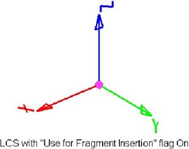
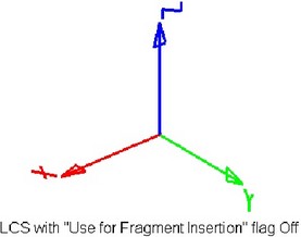
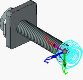
The coordinate systems marked as used for fragment attachment will be displayed in the 3D window in a special way: a sphere is drawn at its origin. By this symbol, it can be distinguished from others.
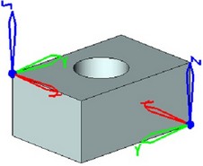
Degrees of Freedom
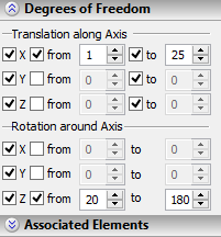
For the LCS which will be used as the source coordinate system upon 3D fragment attachment, it is possible to specify additional conditions in the form of allowed degrees of freedom. They define behavior of the 3D fragment with respect to the fixing LCS. When inserting a 3D fragment, the conditions with degrees of freedom are copied from the LCS parameters to the 3D fragment parameters and subsequently are taken into account when calculating the set of mates of the designed 3D assembly model. There are 6 degrees of freedom of the fragment – 3 translations and 3 rotations with respect to the LCS axes. For each degree of freedom of the LCS, allowable bounds on the fragment displacement can be specified. |
|
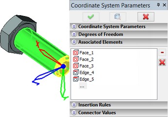
Associated Elements
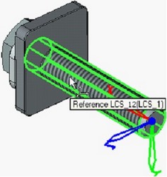
For the LCS it is possible to specify associated, i.e., connected with the LCS elements (vertices, faces, edges, etc.). It will allow a user later on to perform snapping to the given LCS by indicating not the LCS itself, but the elements connected with the LCS. For example, if for the “external” LCS created in the fragment of the bolt, faces and edges of the bolt are specified as associated elements, then in the assembly when attaching a nut to this bolt, it will be sufficient to point at any face or edge of the bolt with the cursor – the LCS connected with these elements will be highlighted and selected as a result.
3D Fragment Insertion Rules upon Snapping to Given LCS
For LCS which is going to be used as the target LCS upon 3D fragment attachment, so-called “insertion rules” can be specified. They imply the necessity of specifying additional transformations upon insertion of the fragment with snapping to the given LCS.
For example, when a nut is snapped to the bolt LCS, it is usually necessary to specify additional translation of the nut along the bolt axis. That is why when designing a bolt model, in the insertion rules for the bolt LCS, it is possible to indicate the necessity of translation along the X-axis.
3D Connector
3D connector represents itself the LCS for which named values are specified. The named values determine information (values of variables) which a connector must pass to the 3D fragments switched to this connector. For example, among the bolt fragments included in the library of the standard T-FLEX CAD elements, 3D fragments containing data about the current diameter of the bolt were created. Upon snapping the fragment-nut (from the same library) to such connector, the nut diameter will be automatically replaced with the value taken from the connector. The image of the 3D connector differs from that of the standard LCS by the form of the axes arrows. Specifying position and direction of the 3D connectors axes is performed in the same way as upon creating the standard LCS. The named connector values are specified in the dialog of the LCS parameters (3D connector). They can be constants (a constant is indicated as an expression for such named value) as well as variables (the name of the variable of the current document is indicated as an expression for such named value). |
|
|
Creating LCS
To create an LCS, use the command "3O: Create Local Coordinate System":
Icon |
Ribbon |
|---|---|
|
3D Model→ Construct→ LCS |
Keyboard |
Textual Menu |
<3O> |
Construct > LCS |
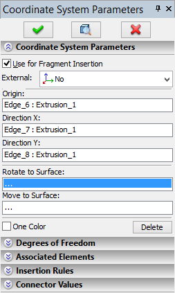
When creating an LCS, the properties window and the command automenu are used together.
To select a geometrical element defining some property of the LCS (the origin, X and Y axis direction, the reorientation surface, etc.) you can simply focus in the respective input box of the properties window. In this case, the option for defining the given parameter activates automatically in the automenu. The option combo box allows setting up filters for geometry elements selection. The opposite is also true: upon activating one of the automenu options, the input focus in the command's properties window automatically switches to the input box of the LCS parameter, corresponding to that option.
Specifying Geometric Characteristics of LCS
Note that geometry elements, defining various LCS parameters (the origin, X and Y axis direction, the reorientation surface, etc.) can be selected in arbitrary order. Those, however, will be applied in the order described earlier in this chapter.
To select a 3D point defining the origin of the LCS, focus in the input box "Origin" of the properties window (the section "LCS parameters"). The following automenu option will become active:
Once the 3D point of the coordinate system origin is selected, the image of the LCS being created is displayed in the 3D window. As the rest of the characteristics are specified, the direction of the LCS axes can be modified. To define the X-axis direction, use the entry "X axis direction" of the properties window and the automenu option:
The Y-axis direction of the LCS is defined in the "Y axis direction" entry of the properties window and the automenu option:
|
|
The surface, whose nearest point defines the reorientation of the X-axis of the LCS, is specified in the input box "Rotate to Surface". The respective automenu option is:
![]() <4> Rotate LCS to be orthogonal to Face
<4> Rotate LCS to be orthogonal to Face
To select the tangency surface, use the "Move to Surface" entry of the properties window and the automenu option:
![]() <5> Offset LCS to be tangent to Face
<5> Offset LCS to be tangent to Face
The selected geometry elements (3D node, vertex, edge, etc.) are specified in the respective entries of the properties window. To reject an element, focus in this entry and press the button [Delete]. Moreover, by pressing ![]() or <Esc> it is possible to successively cancel selection of all elements.
or <Esc> it is possible to successively cancel selection of all elements.
To modify axes orientation of an LCS, use the following options:
![]() <A> Rotate LCS around X axis by 90°
<A> Rotate LCS around X axis by 90°
![]() <O> Rotate LCS around Y axis by 90°
<O> Rotate LCS around Y axis by 90°
![]() <Z> Rotate LCS around Z axis by 90°
<Z> Rotate LCS around Z axis by 90°
The cyclical reassignment of the axes of an LCS is done by the option:
![]() <Tab> Change LCS axes orientation
<Tab> Change LCS axes orientation
Additionally, in the command's properties window you can specify the parameters required when using this LCS for positioning fragments. The detailed description of those parameters is provided in the section "LCS parameters" of this chapter.
Once the desired LCS is built, confirm its creation by ![]() (in the properties window or in the command automenu). To reject creation of the given LCS, use the automenu option:
(in the properties window or in the command automenu). To reject creation of the given LCS, use the automenu option:
![]() <F> Reset target LCS
<F> Reset target LCS
Before confirming the LCS creation with the help of ![]() in the command's properties window, the LCS characteristics (see below) necessary for snapping 3D fragments can be specified.
in the command's properties window, the LCS characteristics (see below) necessary for snapping 3D fragments can be specified.
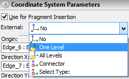
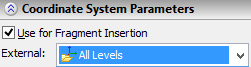
Choosing LCS Visibility Mode in Assembly
When inserting the current document into an assembly as a 3D fragment, the drop down list of the parameter “External” in the group “Coordinate System Parameters” of the command's properties window is used for selecting LCS visibility mode: -No. LCS will be always invisible in assembly; -One level. LCS will be visible in assembly on one level; -All levels. LCS will be visible in assembly on all levels; |
|
-Connector. LCS will be invisible in assembly but available for snapping to it (this option is usually used for 3D connectors).
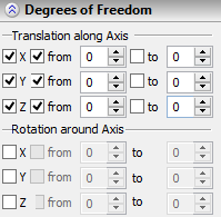
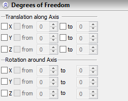
LCS as Source Coordinate System of 3D Fragment. Specifying Degrees of Freedom
To utilize the LCS being created as the source LCS of the fragment (upon inserting the current document into an assembly as a 3D fragment), it is necessary to set on the flag “Use for Fragment Insertion” found in the command's properties window, in the group “Coordinate System Parameters”. By default, this flag is turned on. When the flag “Use for Fragment Insertion” is on, in the group “Degrees of Freedom” it is possible to additionally indicate degrees of freedom of the 3D fragment when given LCS is used as the source fixing LCS. There are 6 degrees of freedom for a fragment – 3 translations and 3 rotations with respect to LCS axes. By default, all degrees of freedom are forbidden – the switched off flags found next to the strings of all degrees of freedom manifest about that. |
|
|
|
For enabling any of the degrees of freedom, it is necessary to set on the flag to the left of the corresponding string. In this case, the fragment can move along the given axis of the LCS (or rotate around the given axis of the LCS) with no restrictions. For specifying start and/or end limits of permissible motion by allowed degrees of freedom, it is necessary to set on flags before the fields “from” and/or “to” and specify desired value in the opened entry field. Note that for rotation around the LCS axes, two (start and end) limits of motion have to be specified at the same time. For translation along the axis, the limits can be specified independently (for example, only start, or only end limit). |
|
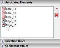
Selection of Associated Elements
For specifying associated elements, the command's property window (group “Associated Elements”) and automenu can be used.
To specify associated elements with the help of the automenu, it is necessary to turn on the option:
![]() <E> Select Associated Elements
<E> Select Associated Elements
This option allows a user to select the associated elements for the LCS just by picking them in 3D window. The drop down list of the option contains filters for choosing the elements. The selected 3D elements are put into the list “Associated Elements”. The option For removing selected elements, the buttons to the right of the list are used. The button |
|
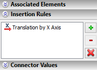
Specifying 3D Fragment Insertion Rules upon Attaching to Given LCS
Additional transformations of translation/rotation, which the system automatically prompts a user to carry out when the fragment is attached to given LCS, can be specified in the group “Insertion Rules” found in the command's properties window.
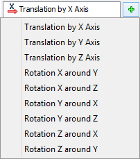
To create a new rule, press the button ![]() . Upon pressing this button, a drop down menu appears in which a desired type of transformation needs to be chosen. The selected transformation is added to the list.
. Upon pressing this button, a drop down menu appears in which a desired type of transformation needs to be chosen. The selected transformation is added to the list.
|
|
For removing one of the specified transformations, choose it in the list and press the button ![]() . Pressing the button
. Pressing the button ![]() will lead to deletion of all transformations at once.
will lead to deletion of all transformations at once.
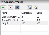
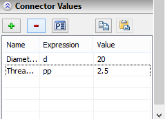
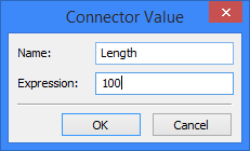
Specifying Named Values for 3D Connector
When creating 3D connector the named values are specified in the group “Connector Values” in the properties window for the LCS. In the list found in the given group of the properties window, the names of the named values of the connector, their expressions and current values are indicated. The buttons located above the list are used for filling in the list of the named values. To add a new named value to the list, the button |
|
It is recommended to specify “meaningful” names for the named connector values sticking to the same name creation rules in all 3D models. This will simplify the setup of the connection between the connector values and external variables of the fragments snapped to it. For example, at first sight complicated names like “DiameterOuterMetricThread”, “ThreadPitchMetric”, “LengthInnerMetricThread”, “LengthInnerInchThread” used in the standard T-FLEX CAD libraries, are actually made up according to the common to all libraries rules and exactly show what information is transferred by the given connector value.
Pressing the button ![]() removes the named value selected in the list at the moment of pressing the button.
removes the named value selected in the list at the moment of pressing the button.
By pressing the button ![]() , it is possible to rename already created named connector value or the expression specified for connector value.
, it is possible to rename already created named connector value or the expression specified for connector value.
The button ![]() allows a user to copy all named connector values and their expressions to the clipboard.
allows a user to copy all named connector values and their expressions to the clipboard.
The button ![]() adds the lines located in the clipboard of the system to the list of the named values (if in the list there are no named values with the same names). Copying the named values via clipboard works in the framework of the same instance of T-FLEX CAD application. Thus, it is possible to copy the named values from one document to another.
adds the lines located in the clipboard of the system to the list of the named values (if in the list there are no named values with the same names). Copying the named values via clipboard works in the framework of the same instance of T-FLEX CAD application. Thus, it is possible to copy the named values from one document to another.
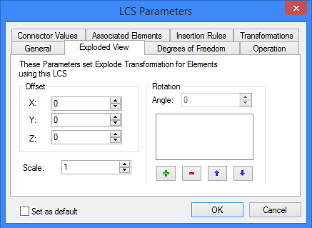
LCS parameters
Parameters of an LCS are defined in the dialog box invoked by the option:
![]() <P> Set entity parameters.
<P> Set entity parameters.
Some parameters of this dialog are common across all 3D elements. Their detailed description is provided in the chapter "General parameters of 3D elements".
Other parameters of the given dialog duplicate parameters of the LCS properties window already described above. Thus, only those LCS parameters which were not mentioned in the previous section of this chapter will be described in this section.
You can define the following parameters of an LCS on the tab "General":
Comment. This parameter allows specifying a text string – the description of the given LCS. The comment helps selecting a coordinate system from the list of those available for positioning, when applying a 3D fragment.
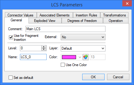
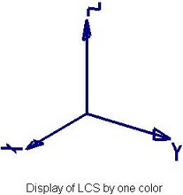
Use One Color. This flag is responsible for the LCS viewing colors. When it is turned off, the LCS axes are drawn with different colors. Each axis color (red, green, or blue) corresponds to the color of the global axis. When the flag is turned on, the LCS is drawn with one color (“Color” parameter).
On the tab "Exploded View", you can specify the transformations that will be applied to 3D fragments attached to the given LCS in the exploding mode (the command "Tools|Exploded View").