Adaptive 3D Fragments


Adaptive 3D Fragments |
|
An adaptive fragment in T-FLEX CAD is a 3D fragment with the external parameters being not only external variables, but also geometrical elements. A geometrical parameter can be represented by any model elements (a solid, 3D node, 3D path, 3D profile, workplane, LCS, vertex, edge, face, loop). The idea of the approach is using the substitution geometry of an assembly element instead of the original geometry of the external parameter in the structure of an adaptive 3D fragment when regenerating a particular instance of its model. In this way, the 3D fragment acts as if "adapting" to the objects of the assembly model. For example, adaptive 3D fragments are used in special operations of inserting holes and creating stamped features in the appropriate system commands.
To use a 3D fragment as an adaptive model element, define in advance the set of geometrical parameters that can have relations with objects of an assembly model. Just like a set of external variables, a set of geometrical parameters is defined in the document of the given 3D fragment. The system allows defining geometrical parameters and their values actually at the time of inserting or editing a 3D fragment; however, the created relations will be used in this case only in the current assembly model. In such a case, this information will not be saved in the 3D fragment's document. When inserting an adaptive 3D fragment, the user specifies the values of geometrical parameters. The type of the instantiating object must be the same as the type of the object which is the parameter of the 3D fragment. For example, the instantiating value for a 3D profile can be defined only by a 3D profile.
The use of geometrical parameters for a 3D fragment can be combined with use of external variables and attachment coordinate systems. However, while doing so, keep in mind the specifics of instantiating a parameter object, as the substitution affects both the geometry of the adaptive parameter and its position in the assembly. As we know, the position of a 3D fragment in an assembly is defined by the source and target coordinate systems. Those coordinate systems can be specified by LCS or defaulted to the global coordinate systems of a 3D fragment and an assembly models.
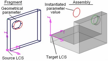
When instantiating the geometrical parameter, the system runs a "reverse" transformation by carrying the object from the assembly to the 3D fragment model, from the target LCS of the assembly towards the source LCS of the 3D fragment.
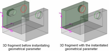
Upon instantiating the values, an adaptive 3D fragment is regenerated and inserted into the assembly model. The user needs to insure correct orientation of the parameter object instances to have them positioned according to the design intent upon embedding in the 3D fragment model.
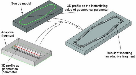
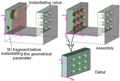
On the diagrams below, a 3D profile instance substitutes the original profile defining a hole in a wall of a 3D fragment. According to the intent, the new profile instance will serve for creating an array of holes in a wall of a 3D fragment. Among the two possibilities, in the first case the profile instance will be suitable for creating holes upon embedding in the 3D fragment model, while not so in the second case.
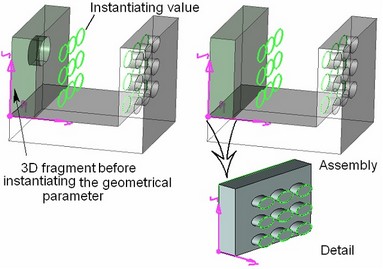
Let's review in details what happens with the 3D fragment model in the second case. Since a different instance of the 3D profile is used in this case, oriented differently with respect to the target LCS, then the result differs in the final position of the profile in the 3D fragment model. The detail view clearly shows that protruding the array of profiles in the second case does not lead to hole creation (to demonstrate that, the second operand of the Boolean subtraction was left in the scene); therefore, the 3D fragment is inserted in the assembly without holes in its wall.
If, upon inserting an adaptive 3D fragment, it is necessary to use the source coordinate system, then make sure that it is created based on 3D fragment model elements (3D nodes, edges, vertices) that are independent of the external geometrical parameters. In other words, the parents of the source coordinate system shall not change upon instantiating adaptive elements.
Setting up adaptive 3D fragment
To make a 3D model suitable for use as an adaptive 3D fragment, a set of objects (adaptive elements) needs to be defined, whose geometry will be driven by the assembly objects.
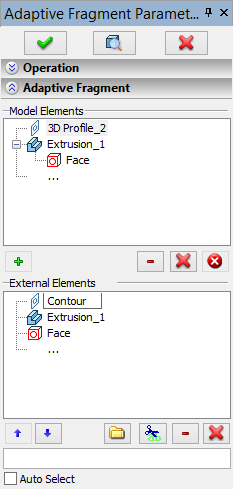
To specify the list of geometrical parameters, use the command "3U: Set Adaptive Fragment Parameters". The command is called as:
Icon |
Ribbon |
|---|---|
|
Tools → Adaptivity → Adaptive Fragment 3D Model → Advanced → Adaptive fragment |
Keyboard |
Textual Menu |
<3U> |
Tools > Adaptive Fragment |
Upon calling the command, you can fill in the item "Name" in the properties window (optional). The entered string will be the name of the 3D fragment in the model. If the name is not specified, the default "Part_No" is used in the model. The "Comment" item may contain a text explaining the intended uses of the given 3D fragment.
If a fragment document is equipped with a slide, this slide will be used as the icon of the 3D fragment in the model tree of the assembly document. Icons are created in the command "Tools|Special Data|Preview".
To add a new object to the list of adaptive elements, select it in the 3D view window or in the model tree. The selected element appears in the upper list, "Model Elements", in the properties window. Upon selecting an object, the system automatically adds to the list the topological elements of that object (edges, vertices, faces) that are referenced by the object's children.
The "Model Elements" list provides an intuitive display of interrelations of the selected object with its children and adds a capability of selecting elements that are not at the top level of the model hierarchy as the geometrical parameters.
When creating or editing a 3D fragment in the assembly context (the "Top-down" design flow), the "Model Elements" list is built automatically. The system creates this list based on the objects that are referencing assembly model elements (3D profiles, workplanes, 3D nodes, etc.). If a 3D fragment is intended for insertion in other assembly models, the user can compose the list of external geometrical parameters by using the already built "Model Elements" list.
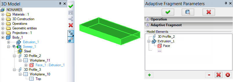
To give an example of composing a list of external geometrical parameters, let's consider a 3D fragment that defines creation of a stamped feature (see the diagram at the beginning of the chapter). To create a groove in the assembly, all that is necessary is just to specify the body face in which the groove is to be extruded, and the trajectory defining its contour. The first element in the "Model Elements" list will be the 3D profile serving as the base for creating the sweep. Let's designate the "Extrusion_0" as the second element in the list. In this way, the system adds to the list the face of this operation, since the face is the parent element for the "Sweep_1" operation.
The set of object types allowed for selection is defined by the option:
![]() <V> Select type of parameter
<V> Select type of parameter
The drop-down list will help setting up the internal command filters for selecting objects of a certain type: workplane, worksurface, coordinate system, operation, 3D path, 3D node, 3D profile.
The default active option in the automenu is:
![]() <M> Show parameter in Fragment document
<M> Show parameter in Fragment document
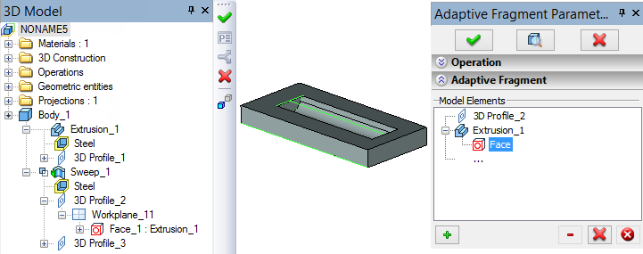
It enables highlighting of the objects that are not at the top of the model tree hierarchy. For example, if the given operation is active, then upon selecting a face of the operation "Extrusion_0" in the list of objects, this face will be highlighted in the model (at the same time, all children of "Extrusion_0" will be temporary removed from the 3D scene).
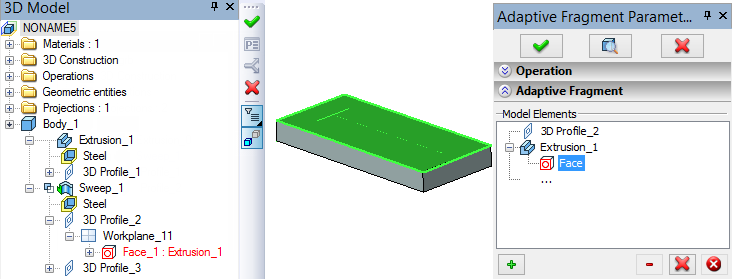
If the option is not active, then highlighting will only work if the current element in the list is a top-level operation. Therefore, in this particular example, the Extrusion_0 and its face will not be highlighted in the model.
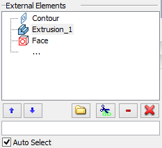
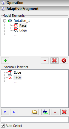
The next required action is composing the "External Elements" list. This list gets the elements from the "Model Elements" list, that will be instantiated upon inserting the 3D fragment into an assembly model.
We recommend putting in the list of external parameters all topological children of the model object, that were entered in the upper list, and instantiate them as values in the assembly. Suppose, the external parameters list of an adaptive 3D fragment does not contain all topological children of the selected model object, or some of those objects are not instantiated upon inserting this fragment into an assembly. In this case, upon regenerating the 3D fragment model (at the time of inserting it in the assembly) errors will occur when creating the operations (or other objects) that are based on the uninstantiated topological elements. To avoid a large number of unnecessary dependent elements in the list of geometrical parameters, prefer building the 3D fragment model in such a way that the model elements used as geometrical parameters are at the highest possible level in the model tree structure. Move elements by selecting in the upper list and pressing the graphic button
|
|
Example of creating adaptive 3D fragment
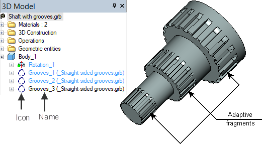
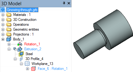
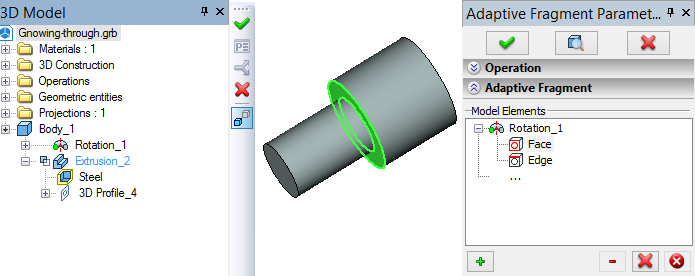
Let's review a simple example – a body in a 3D fragment file created from three operations: rotation, extrusion and a boolean operation. The “Extrusion_1” contour is constructed on a workplane that references an edge of “Rotation_0”, extrusion direction – along the normal to the profile plane.
We need to create an adaptive 3D fragment that will be creating a grooving based on a round edge selected on any assembly operation.
To compose the "Model Elements" list, simply select "Rotation_0" in the tree.Its edge and face that are parents of "Extrusion_1" will be added to the list automatically. "Extrusion_1" in this case is the operation that is used for creating the grooving.
The next step will be creating the list of external parameters. It's enough just to move the edge and face into the lower list, while the operation on which the grooving is to be created will be determined by the system automatically. Fill in the comment entries for each element and set the "Auto Select" flag for the face. Let us remind that instantiating upon inserting a 3D fragment is done only for the objects that are entered in the list of external parameters. In a general case, the "Model Elements" list may contain the elements that are not used as the external parameters. If in the current example the edge would have not been moved to the list of external parameters, then it would not be possible to specify what particular edge of the assembly to use for creating the grooving. In other words, the parent would have not been defined for Workplane_3 in the fragment and, therefore, the Extrusion_1 operation would have not been created.
The contents of the adaptive elements list can be managed by graphic buttons in the properties window:
- for the "Model Elements" list:
![]() - Delete. Deleting current element;
- Delete. Deleting current element;
![]() - Delete all. Deleting all elements;
- Delete all. Deleting all elements;
![]() - Delete unused. Deleting unused elements. This button becomes accessible if the list contains objects deleted from the model. Such objects are marked in the list by the icon
- Delete unused. Deleting unused elements. This button becomes accessible if the list contains objects deleted from the model. Such objects are marked in the list by the icon ![]() .
.
- for the “External Elements” list:
![]()
![]() - Up/Down. Moving current element around the list;
- Up/Down. Moving current element around the list;
![]() - New Folder. Creating a new folder. The list of external parameters can be organized into a tree structure, by distributing the list elements over different levels or over different folders in one level. When inserting a 3D fragment into a model, its geometrical parameters will be displayed according to the defined structure;
- New Folder. Creating a new folder. The list of external parameters can be organized into a tree structure, by distributing the list elements over different levels or over different folders in one level. When inserting a 3D fragment into a model, its geometrical parameters will be displayed according to the defined structure;
![]() – Rename. Renaming selected external parameter. For each external parameter you can assign the meaningful name;
– Rename. Renaming selected external parameter. For each external parameter you can assign the meaningful name;
![]() - Delete. Deleting current element;
- Delete. Deleting current element;
![]() - Delete All. Deleting all elements.
- Delete All. Deleting all elements.
Elements of the external parameters list can be renamed. To do this, click ![]() at an element's name, and then edit the parameter's name.
at an element's name, and then edit the parameter's name.
Inserting adaptive 3D fragment, instantiating adaptive elements
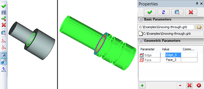
When invoking the command "3F: Insert 3D Fragment" for a 3D fragment with defined adaptive elements, the default focus is set on the "Value" entry of the first external parameter in the properties window, in the "Geometric Parameters" section. A bar below the list displays the comment to the current parameter. To define the value, in the 3D view window or in the model tree select an object of the same type as the external geometrical parameter of the 3D fragment.
If the 3D fragment selected for inserting has the geometrical parameters preset, the following option will be available in the auto menu:
![]() <R> Show Geometric Parameters of Adaptive Fragment
<R> Show Geometric Parameters of Adaptive Fragment
It allows viewing the 3D model of the fragment being inserted in an additional window, with the current external parameter highlighted. When selecting an object, the system also picks the instantiating values for those parents of the current parameter that are flagged "Auto Select". The automatic instantiating can be altered by selecting a different model object.
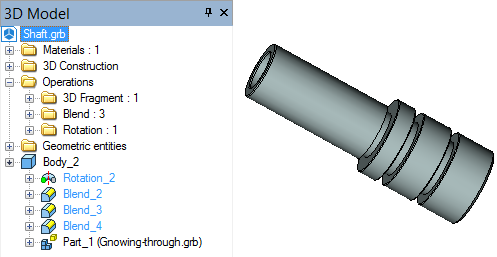
Use the ![]() option to complete insertion of a 3D fragment. If errors are encountered in the 3D fragment's model due to the specified values of the geometrical parameters, then the 3D fragment will not appear in the scene and the appropriate messages will be output in the diagnostics window.
option to complete insertion of a 3D fragment. If errors are encountered in the 3D fragment's model due to the specified values of the geometrical parameters, then the 3D fragment will not appear in the scene and the appropriate messages will be output in the diagnostics window.
Defining adaptive elements of an existing fragment
The system supports defining the list of external parameters and their instantiating values for both inserting new fragments and editing existing fragments in an assembly. To add an additional parameter, call the command for editing a 3D fragment. In the "Geometric Parameters" section of the properties window, press the button ![]() and select the 3D fragment model's element to become an external parameter. The next step will be either instantiating its value or adding more parameters to the list. The difference of this approach from the steps described in the "Setting up adaptive 3D fragment" section is that such changes in the list are remembered only in the current assembly. When inserting this 3D fragment into another assembly model, the elements added to the list will not be available. Therefore, any 3D fragment of an assembly model can be converted to an adaptive 3D fragment, and the predefined list of geometrical parameters of an existing adaptive 3D fragment can be extended.
and select the 3D fragment model's element to become an external parameter. The next step will be either instantiating its value or adding more parameters to the list. The difference of this approach from the steps described in the "Setting up adaptive 3D fragment" section is that such changes in the list are remembered only in the current assembly. When inserting this 3D fragment into another assembly model, the elements added to the list will not be available. Therefore, any 3D fragment of an assembly model can be converted to an adaptive 3D fragment, and the predefined list of geometrical parameters of an existing adaptive 3D fragment can be extended.